Page 25
After the 15−second pre−purge period, the SureLight ignitor
warms up for 20 seconds after which the gas valve opens
for a 4−second trial for ignition. The ignitor energizes during
the trial until flame is sensed. If ignition is not proved during
the 4−second period, the control will try four more times with
an inter−purge and warm−up time between trials of 35 sec-
onds. After a total of five trials for ignition (including the ini-
tial trial), the control goes into Watchguard mode. After a
60−minute reset period, the control will begin the ignition
sequence again.
The SureLight control has an added feature that prolongs
the life of the ignitor. After a successful ignition, the Sur-
eLight control utilizes less power to energize the ignitor on
successive calls for heat. The control continues to ramp
down the voltage to the ignitor until it finds the lowest
amount of power that will provide a successful ignition. This
amount of power is used for 255 cycles. On the 256th call
for heat, the control will again ramp down until the lowest
power is determined and the cycle begins again.
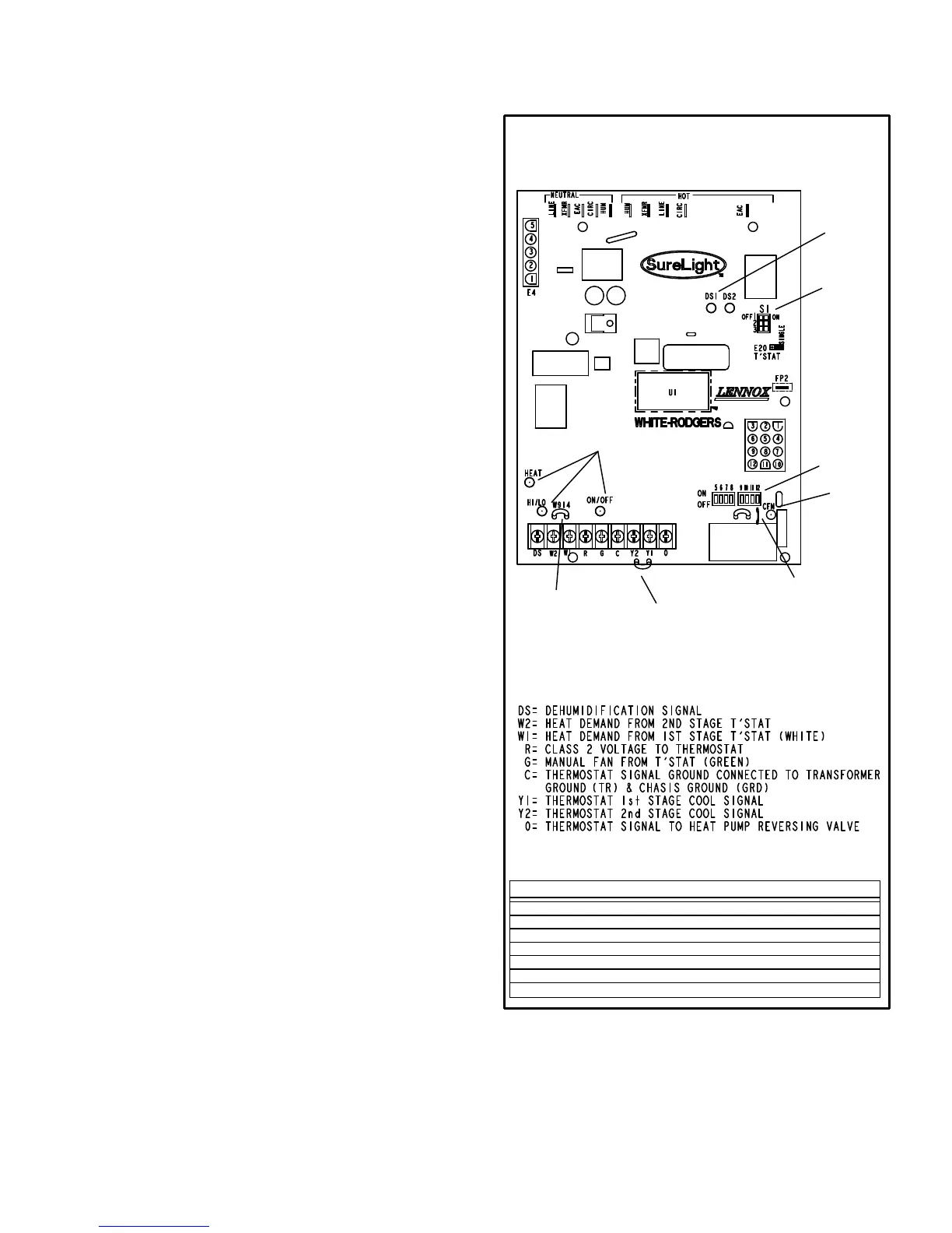
Two Stage Operation / Thermostat Selection Jumper
The control can be utilized in two modes: SINGLE−STAGE
thermostat or TWO−STAGE thermostat. The thermostat
selection jumper E20, located just below dip switches 1
through 3 (figure 4), must be positioned for the particular
application. The jumper is factory set on TWO" for use
with a two−stage thermostat with two stage heat. Re−posi-
tion jumper to SINGLE" for use with a single stage thermo-
stat with two stage heat.
While in the single−stage thermostat mode (single jumper
setting), the burners will always fire on first−stage heat. The
combustion air inducer will operate on low speed and in-
door blower will operate on low heat speed. After a 10 min-
ute recognition period, the unit will switch to second stage
heat. While in the two−stage thermostat mode (two jumper
setting) the burners will fire on first−stage heat. The com-
bustion air inducer will operate on low speed and indoor
blower will operate on low heat speed. The unit will switch
to second−stage heat on call from the indoor thermostat. If
there is a simultaneous call for first and second stage heat,
the unit will fire an first stage heat and switch to second
stage heat after 30 seconds of operation. See Sequence of
Operation flow charts in the back of this manual for more
detail.
TWO−STAGE, VARIABLE SPEED INTEGRATED
CONTROL BOARD
FIGURE 4
DIP
SWITCHES
5 − 12
DIP
SWITCHES
1 − 3
DIAGNOSTIC
LEDs
LED
ON−BOARD
JUMPER W951
(cut when heat pump is
used with FM21)
ON−BOARD
JUMPER W914
(cut when SignatureStat,
CCB1 or Harmony II are
used)
ON−BOARD
JUMPER W915
(cut when two−stage
cooling is used)
LEDs
THERMOSTAT CONNECTIONS (TB1)
DIP SWITCH FUNCTIONS
DIP SWITCH(ES) FUNCTION
1 and 2 Blower Off Delay
3 Second Stage ON Delay (Single−stage t’stat)
4 Not used
5 and 6 Cooling Mode Blower Speed
7 and 8 Blower Speed Adjustment
9 and 10 Cooling Mode Blower Ramping Profile
11 and 12 Heating Mode Blower Speed

 Loading...


