Page 68
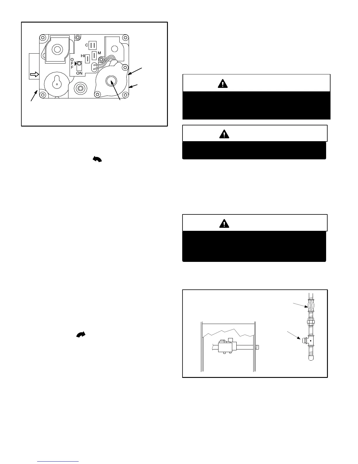
WHITE RODGERS 36E SERIES GAS VALVE
GAS VALVE SHOWN IN OFF POSITION
HIGH FIRE
MANIFOLD
PRESSURE
ADJUSTMENT
ON SIDE
(under cap)
MANIFOLD
PRESSURE
TAP ON SIDE
INLET PRESSURE
TAP ON SIDE
LOW FIRE MANIFOLD
PRESSURE ADJUSTMENT
ON SIDE (under cap)
FIGURE 50
8 − Honeywell VR8205 Gas Valve − Turn knob on gas
valve counterclockwise
to ON. Do not force.
White Rodgers 36E Gas Valve − Switch gas valve lever
to ON. See figure 50 for the White Rodgers 36E
valve.
9 − Replace the upper access panel.
10− Turn on all electrical power to to the unit.
11− Set the thermostat to desired setting.
NOTE − When unit is initially started, steps 1 through 11
may need to be repeated to purge air from gas line.
12− If the appliance will not operate, follow the instructions
Turning Off Gas to Unit" and call your service techni-
cian or gas supplier.
Turning Off Gas to Unit
1 − Set the thermostat to the lowest setting.
2 − Turn off all electrical power to the unit if service is to be
performed.
3 − Remove the upper access panel.
4 − Honeywell VR8205 Gas Valve − Turn knob on gas
valve clockwise
to OFF. Do not force.
White Rodgers 36E Gas Valve − Switch gas valve le-
ver to OFF.
5 − Replace the upper access panel.
C−Safety or Emergency Shutdown
Turn off unit power. Close manual and main gas valves.
D−Extended Period Shutdown
Turn off thermostat or set to UNOCCUPIED" mode. Close
all gas valves (both internal and external to unit) to guaran-
tee no gas leak into combustion chamber. Turn off power to
unit. All access panels and covers must be in place and se-
cured.
IV−HEATING SYSTEM SERVICE CHECKS
A−C.S.A. Certification
All units are C.S.A. (formally A.G.A. and C.G.A. combined)
design certified without modifications. Refer to the
G61MPV Installation Instruction.
B−Gas Piping
CAUTION
If a flexible gas connector is required or allowed by
the authority that has jurisdiction, black iron pipe
shall be installed at the gas valve and extend outside
the furnace cabinet.
WARNING
Do not exceed 600 in−lbs (50 ft−lbs) torque when
attaching the gas piping to the gas valve.
Gas supply piping should not allow more than 0.5"W.C. drop
in pressure between gas meter and unit. Supply gas pipe
must not be smaller than unit gas connection.
Compounds used on gas piping threaded joints should be
resistant to action of liquefied petroleum gases.
C−Testing Gas Piping
IMPORTANT
In case emergency shutdown is required, turn off
the main shut-off valve and disconnect the main
power to unit. These controls should be properly
labeled by the installer.
When pressure testing gas lines, the gas valve must be dis-
connected and isolated. Gas valves can be damaged if
subjected to more than 0.5psig (14" W.C.). See figure 51.
FIGURE 51
MANUAL MAIN SHUT−OFF VALVE
GAS VALVE
CAP
GAS PIPING TEST PROCEDURE
When checking piping connections for gas leaks, use pre-
ferred means. Kitchen detergents can cause harmful corro-
sion on various metals used in gas piping. Use of a specialty
Gas Leak Detector is strongly recommended. It is available
through Lennox under part number 31B2001. See Corp.
8411−L10, for further details.
Do not use matches, candles, flame or any other source of
ignition to check for gas leaks.

 Loading...


