Page 29
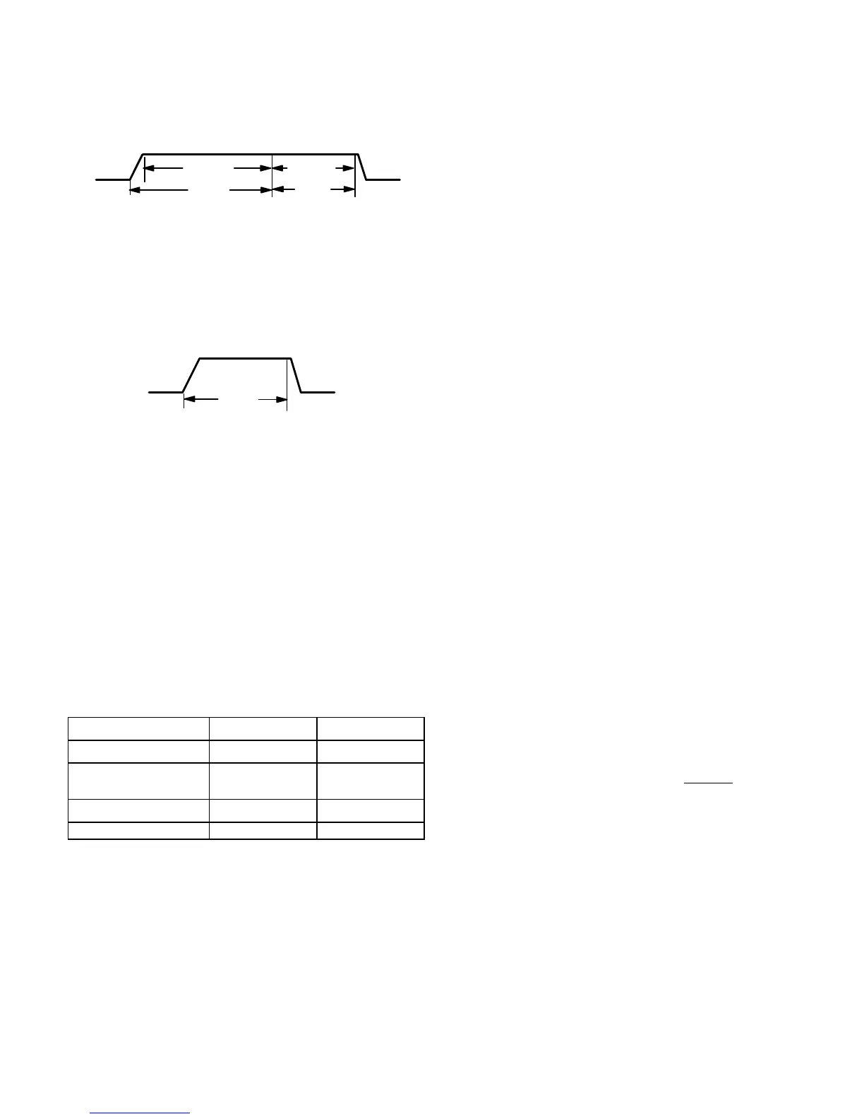
Ramping Option C
Motor runs at 100% until demand is satisfied.
Once demand is met, motor runs at 100% for 60 sec-
onds then ramps down to stop.
OFF
OFF
100% CFM
100% CFM
DEMAND
60 SEC.
Ramping Option D
Motor runs at 100% until demand is satisfied.
Once demand is met, motor ramps down to stop.
OFFOFF
100% CFM
COOLING
DEMAND
Switches 11 and 12 −− Heating Mode Blower Speed −−
Switches 11 and 12 are used to select second stage heat-
ing mode blower motor speed (first stage heating blower
speed is 91% of second stage). The unit is shipped from the
factory with the dip switches positioned for medium low (2)
speed indoor blower motor operation during the heating
mode. The table below provides the heating mode blower
speeds that will result from different switch settings. Refer
to blower data tables at the front of this manual for corre-
sponding cfm values.
TABLE 11
Heating Mode Blower Speeds
Speed
Switch 11 Switch 12
1 − Low On On
2 − Medium Low
(Factory)
Off On
3 − Medium High On Off
4 − High Off Off
On−Board Jumper W914
On−board jumper W914, which connects terminals DS and
R on the integrated control board, must be cut when the fur-
nace is installed with the Harmony II zone control board,
the CCB1 EfficiencyPlus humidity control or the Lennox
SignatureStat.t If the jumper is left intact the PMW signal
from the Harmony II control will be blocked and also lead to
control damage. The SignatureStat and CCB1 will not op-
erate unless the jumper is cut. Refer to table 21 for opera-
tion sequence in applications including a G61MPV, CCB1
and single−speed outdoor unit. Table 22 gives the opera-
tion sequence in applications with a two−speed outdoor
unit. See table 23 for applications for a G61MVP, Signatu-
reStat and single−speed outdoor unit and table 24 for ap-
plications with a two−speed outdoor unit.
On−Board Jumper W951
On−board jumper W951, which connects terminals R and O
on the integrated control board, must be cut when the fur-
nace is installed in applications which include a heat pump
unit and the FM21 FuelMaster control board. If the jumper
is left intact, terminal "O" will remain energized eliminating
the HEAT MODE in the heat pump.
On−Board Jumper W915
On−board jumper W915, which connects terminals Y1 and
Y2 on the integrated control board, must be cut if two−stage
cooling will be used. If the jumper is not cut the outdoor unit
will operate in first−stage cooling only.
Diagnostic LEDs (DS1 and DS2)
Two diagnostic LEDs are located on the two−stage, vari-
able speed integrated control just to the left of the first bank
of dip switches. These flashing lights correspond with diag-
nostic codes detailed on page 52.
Status LEDs (HEAT, HI/LO, ON/OFF and CFM)
The integrated control includes four LEDs which indicate
operating status. The green ON/OFF LED is lit any time the
blower is operating. The green CFM LED indicates the
blower motor speed. Count the number of blinks between
the two−second pauses to determine the CFM. Each blink
represents approximately 100 CFM. The yellow HI/LO LED
is lit when the W914 (DS to R) jumper has not
been clipped
for SignatureStat, CCB1 or Harmony operation. The yellow
HEAT LED is lit when the indoor blower is operating at the
HEATING speed.

 Loading...


