Page 35
TABLE 20
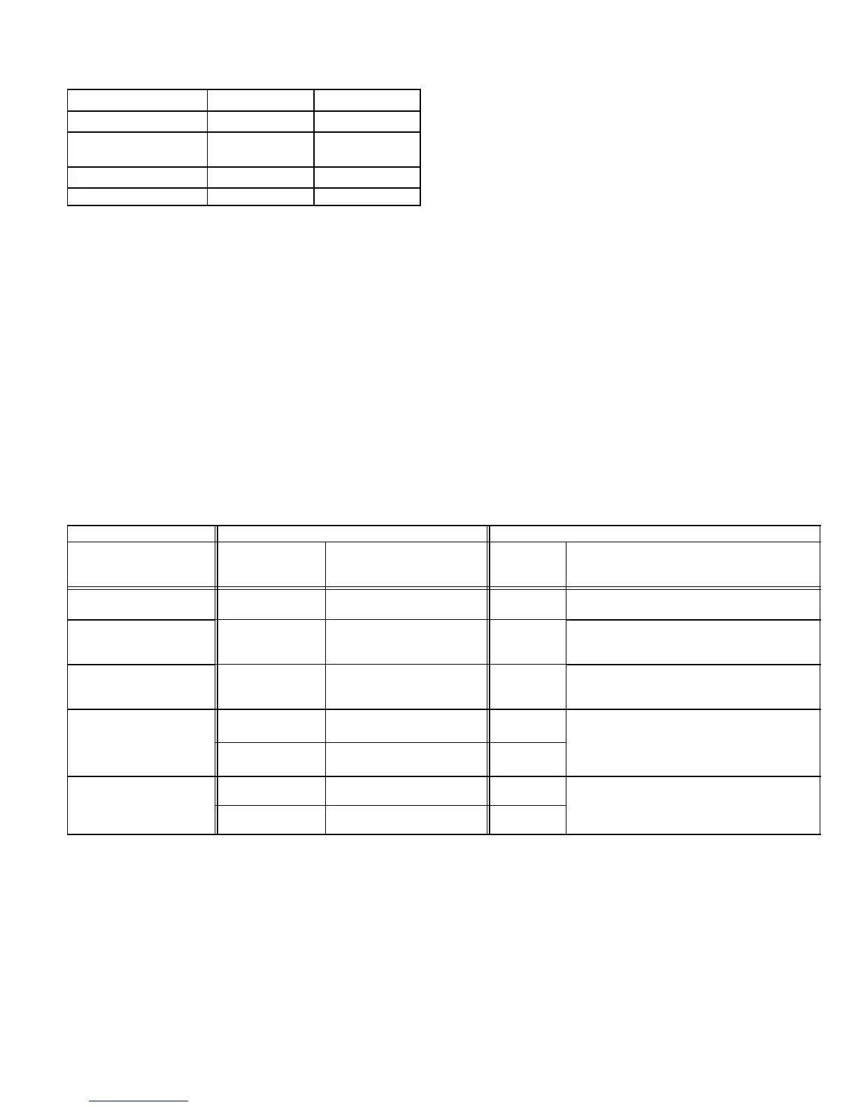
Heating Mode Blower Speeds
Speed
Switch 11 Switch 12
1 − Low On On
2 − Medium Low
(Factory)
Off On
3 − Medium High On Off
4 − High Off Off
On−Board Link W914
On−board link W914 is a clippable connection which con-
nects terminals DS and R on the integrated control board.
W914 must be cut when the furnace is installed with either
the Harmony III zone control board or a thermostat which
features humidity control. If the link is left intact the PWM
signal from the HARMONY III control will be blocked and
also lead to control damage. Refer to tables 21 through 26
for operation sequence in applications including G61MPV
and a thermostat which features humidity control with a
single−stage or two−stage outdoor unit.,
On−Board Link W951
On−board link W951 is a clippable connection which con-
nects terminals R and O on the integrated control board.
W951 must be cut when the furnace is installed in applica-
tions which include a heat pump unit and a thermostat
which features dual fuel use. If the link is left intact, terminal
O" will remain energized eliminating the HEAT MODE in
the heat pump.
On−Board Link W915
On−board link W915 is a clippable connection which con-
nects terminals Y1 and Y2 on the integrated control board.
W915 must be cut if two−stage cooling will be used. If the
link is not cut the outdoor unit will operate in second stage
cooling only.
Status LEDs (SPEED, CFM, E−COM)
The green SPEED LED indicates circulating blower speed
in response to the DS signal. The LED is lit during normal
blower operation and is off during a dehumidification de-
mand. In Harmony III applications, the brightness of the
LED indicates the requested blower speed.
The green CFM LED indicates the blower air flow. Count
the number of blinks between the two−second pauses to
determine the CFM. Each blink represents approximately
100 CFM.
The green E−COM LED indicates that the control is receiv-
ing and processing of commands and inputs. The LED may
flash rapidly or may display a single flash, depending upon
the activity.
TABLE 21
G61MPV, CCB1 and Single−Stage Outdoor Unit
OPERATING MODE SYSTEM DEMAND SYSTEM RESPONSE
System Condition
Thermostat
Demand
*Relative Humidity
(EfficiencyPlus Lights)
Blower CFM
(COOL)
Comments
Normal operation Y1
No demand. Humidity
level is acceptable
COOL
Compressor demand and indoor blower speed
controlled by thermostat demand.
*Call for humidity
removal during
cooling demand
Y1
Humidity level rises above
setpoint. Demand initiated.
70%
of COOL
Call for dehumidification initiated by CCB1 control.
Indoor blower speed reduced by CCB1 control.
Dehumidification
demand satisfied
during cooling demand.
Y1
Humidity level falls below set-
point. No demand
COOL
When humidity demand is satisfied, blower speed
immediately increases to the COOL CFM to has-
ten the end of the cycle.
Call for cooling after call for
humidity
removal.
None
Humidity level above setpoint.
Demand initiated.
Off
Dehumidification mode begins when relative hu-
midity is greater than setpoint.
Y1
Humidity level above setpoint.
Demand initiated.
70%
of COOL
Humidity demand
satisfied between
thermostat demands (unit
off cycle).
None Over setpoint (1 or more) Off
While unit is not operating (no thermostat de-
mand), slide switch is moved down and back up.
Blower operates at COOL CFM.
Y1 Change to acceptable COOL
NOTE − When changing unit mode of operation from cooling to heating, indicating lights that are on will stay on until the first thermostat heating
demand.
* Reduced blower speed is 70% of COOL

 Loading...


