Page 52
Use the following steps to correctly size vent pipe diameter.
1 − Determine the vent termination and its corresponding
equivalent feet value according to table 35.
2 − Determine the number of 90° elbows required for both
indoor and outdoor (e.g. snow riser) use. Calculate the
corresponding equivalent feet of vent pipe.
3 − Determine the number of 45° elbows required for both
indoor and outdoor use. Calculate the corresponding
equivalent feet of vent pipe.
4 − Determine the length of straight pipe required.
5 − Add the total equivalent feet calculated in steps 1
through 4 and compare that length to the maximum
values given in table 37 for the proposed vent pipe di-
ameter. If the total equivalent length required exceeds
the maximum equivalent length listed in the appropri-
ate table, evaluate the next larger size pipe.
IMPORTANT
Do not use screens or perforated metal in exhaust
terminations. Doing so will cause freeze−ups and
may block the terminations.
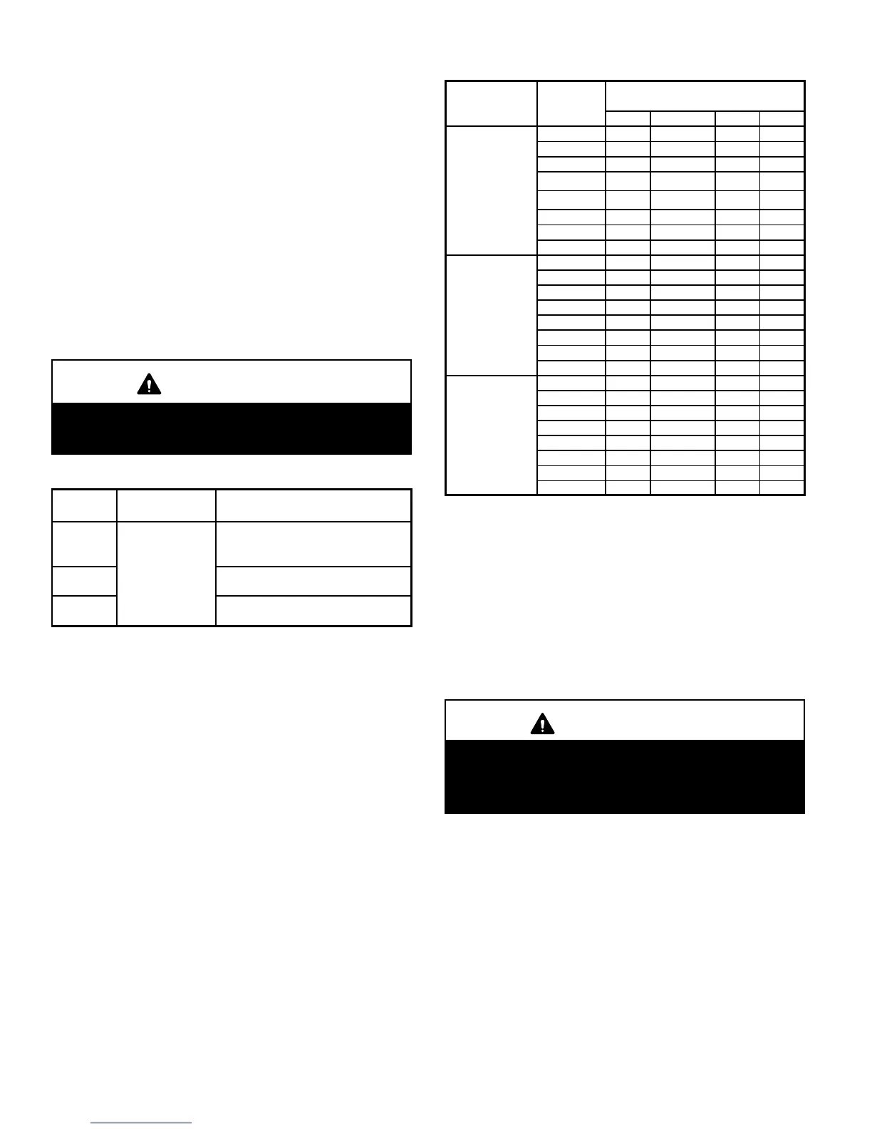
TABLE 36
MINIMUM VENT PIPE LENGTHS
G61MPV
MODEL
MIN. EQUIV.
VENT LENGTH
EXAMPLE
045, 070,
071, 090,
091
15 ft.*
5 ft. plus 2 elbows of 2", 2−1/2", 3"
or 4" diameter pipe
110, 111**
5 ft. plus 2 elbows of 2−1/2" 3" or 4"
diameter pipe
135***
5 ft. plus 2 elbows of 3" or 4"
diameter pipe
*Any approved termination may be added to the minimum equivalent length
listed.
**G61MPV−60C−110 must have 90° street ell (supplied) installed directly into
unit flue collar.
***G61MPV−60D−135 must have 3" to 2" reducing ell (supplied) installed direct-
ly into unit flue collar.
TABLE 37
MAXIMUM VENT PIPE LENGTHS
ALTITUDE
G61MPV
MODEL
MAXIMUM EQUIVALENT VENT
LENGTH FEET
2" dia. 2−1/2" dia. 3" dia. 4" dia.
0 − 4500
(0 − 1371 m)
045 59 65 77 234
070 59 65 78 214
071
†
59 65 78 214
090
26 42 72 204
091
†
26 42 72 204
110* n/a 32 72 179
111
†
n/a 32 72 179
135**
‡
n/a n/a 61 160
4501−7500
(1372−2286 m)
045 59 65 77 234
070 59 65 78 214
0701
†
59 65 78 214
090 26 42 72 204
091
†
26 42 72 204
110* n/a 32 72 179
111
†
n/a 32 72 179
135**
‡
n/a n/a 46 160
7501 − 10000
(2287 − 3048
m)
045 59 65 77 234
070 59 65 78 214
071
†
59 65 78 214
090 26 42 72 204
091
†
26 42 72 204
110* n/a 32 72 179
111
†
n/a 32 72 179
135**
‡
n/a n/a 46 160
n/a −− Not allowed.
*G61MPV−60C−110 must have 90° street ell (supplied) installed directly into
unit flue collar.
**G61MPV−60D−135 must have 3" to 2" reducing ell (supplied) installed directly
into unit flue collar.
†On G61MPV−071, −091 and −111 units, sweep elbows must be used for all
90° elbows in the venting system when 2", 2−1/2" or 3" vent pipe is used.
Sweep elbows are recommended for use in vent systems of other
G61MPV units.
‡
On
G61MPV−60D−135
units,
sweep
elbows
must
be
used
for
all
90°
elbows
in
the
vent
system
when
3"
pipe
is
used.
B−PVC Joint Cementing Procedure
All cementing of joints should be done according to the
specifications outlined in ASTM D 2855.
WARNING
DANGER OF EXPLOSION!
Fumes from PVC glue may ignite during system
check. Allow fumes to dissipate for at least 5 minutes
before placing unit into operation.
1 − Measure and cut vent pipe to desired length.
2 − Debur and chamfer end of pipe, removing any ridges
or rough edges. If end is not chamfered, edge of pipe
may remove cement from fitting socket and result in a
leaking joint.
3 − Clean and dry surfaces to be joined.
4 − Test fit joint and mark depth of fitting on outside of pipe.
5 − Uniformly apply a liberal coat of PVC primer for PVC or
use a clean dry cloth for ABS to clean inside socket
surface of fitting and male end of pipe to depth of fitting
socket.

 Loading...


