Page 61
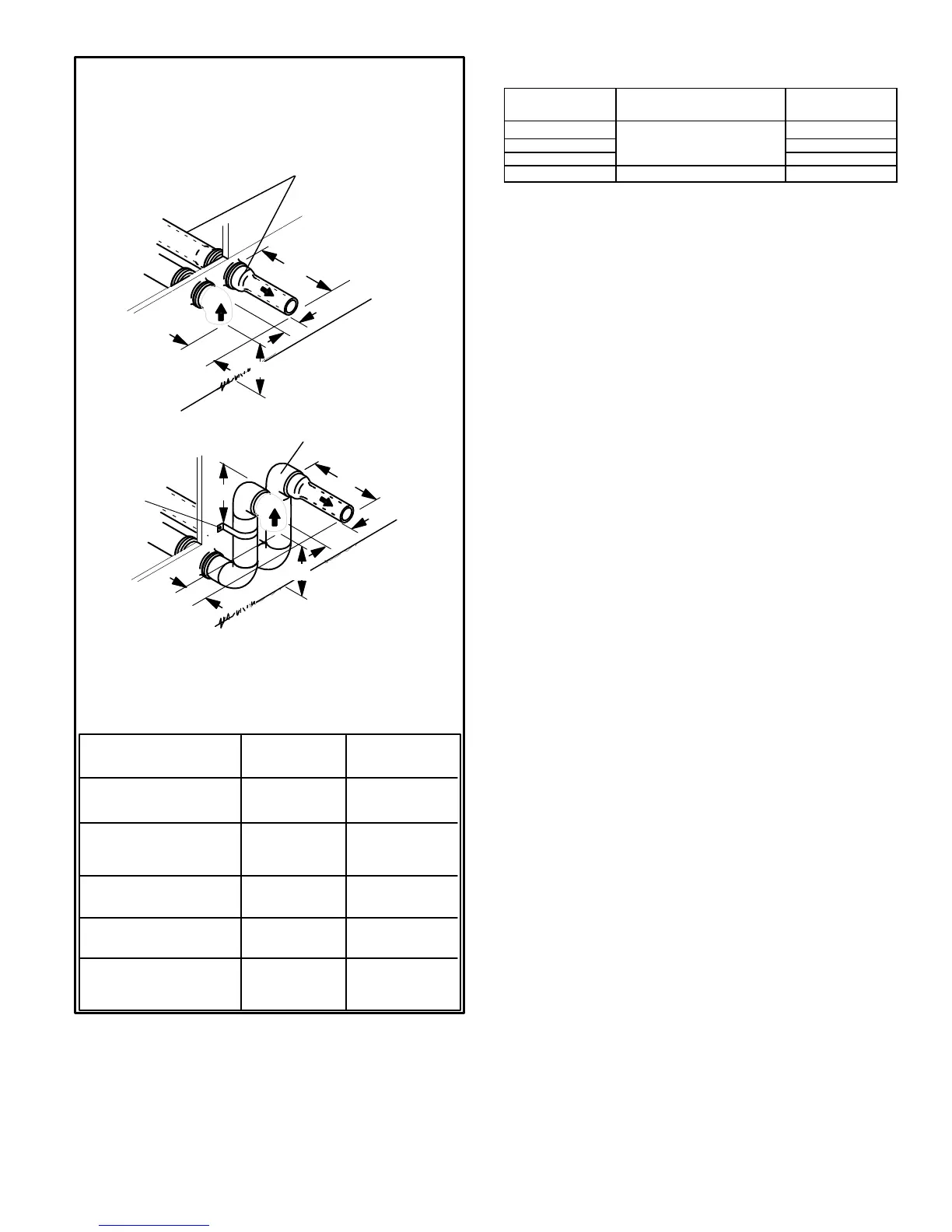
FIGURE 34
FIELD SUPPLIED WALL TERMINATION OR
(15F74) WALL RING TERMINATION KIT
With INTAKE ELBOW
See venting table 37 for maximum venting lengths with this
arrangement.
* Use wall support every 24" (610 mm). Use two wall supports if
extension is greater than 24" (610 mm) but less than 48" (1219 mm).
NOTE − One wall support must be 6" (152 mm) from top of each pipe
(intake and exhaust)
2" (51mm)
Vent Pipe
3" (76mm)
Vent Pipe
12" (508MM) 12" (508MM)
6" (152MM) 6" (152MM)
6" (152MM)
12" (305MM) 20" (508MM)
6" (152MM) 6" (152MM)
6" (152MM)
A−Minimum clearance
above grade or average
snow accumulation
B−Maximum horizontal
separation between
intake and exhaust
C−Minimum from
end of exhaust to
inlet of intake
D−Maximum exhaust
pipe length
E−Maximum wall support
distance from top of each
pipe (intake/exhaust)
NOTE − FIELD PROVIDED
REDUCER MAY BE
REQUIRED TO ADAPT
LARGER VENT PIPE SIZE
TO TERMINATION
D
B
C
SIZE TERMINATION
PER TABLE 38
1/2" (13mm) ARMAFLEX
INSULATION IN UN-
CONDITIONED SPACE
STRAIGHT
APPPLICATION
B
C
D
* WALL
SUPPORT
1/2" (13mm) ARMAFLEX INSULATION
IN UNCONDITIONED SPACE
E
EXTENDED
APPLICATION
A
A
TABLE 38
EXHAUST PIPE TERMINATION SIZE REDUCTION
G61MPV
MODEL
Exhaust Pipe Size
Termination
Pipe Size
045, 070, 071
2" (51mm), 2−1/2" (64mm),
3" (76mm) or 4" (102mm)
1−1/2" (38mm)
090, 091 2" (51mm)
110, 111 2" (51mm)
135
3" (76mm) or 4" (102mm)
2" (51mm)
5. On field supplied terminations for side wall exit, ex-
haust piping may extend a maximum of 12 inches
(305mm) for 2" PVC and 20 inches (508mm) for 3"
(76mm) PVC beyond the outside wall. Intake piping
should be as short as possible. See figures 33 and 34.
6. On field supplied terminations, a minimum distance
between the end of the exhaust pipe and the end of
the intake pipe without a termination elbow is 8" and a
minimum distance of 6" with a termination elbow. See
figures 33 and 34.
7. If intake and exhaust piping must be run up a side wall
to position above snow accumulation or other ob-
structions, piping must be supported every 24"
(610mm) as shown in figures 33 and 34. In addition,
close coupled wall termination kits must be extended
for use in this application. See figures 40 and 41.
When exhaust and intake piping must be run up an
outside wall, the exhaust piping must be terminated
with pipe sized per table 38.The intake piping may be
equipped with a 90° elbow turndown. Using turndown
will add 5 feet (1.5m) to the equivalent length of the
pipe.
8. Based on the recommendation of the manufacturer, a
multiple furnace installation may use a group of up to
four terminations assembled together horizontally, as
shown in figure 37.

 Loading...


