Page 30
ÉÉÉÉÉÉÉÉÉÉÉÉÉ
ÉÉÉÉÉÉÉÉÉÉÉÉÉ
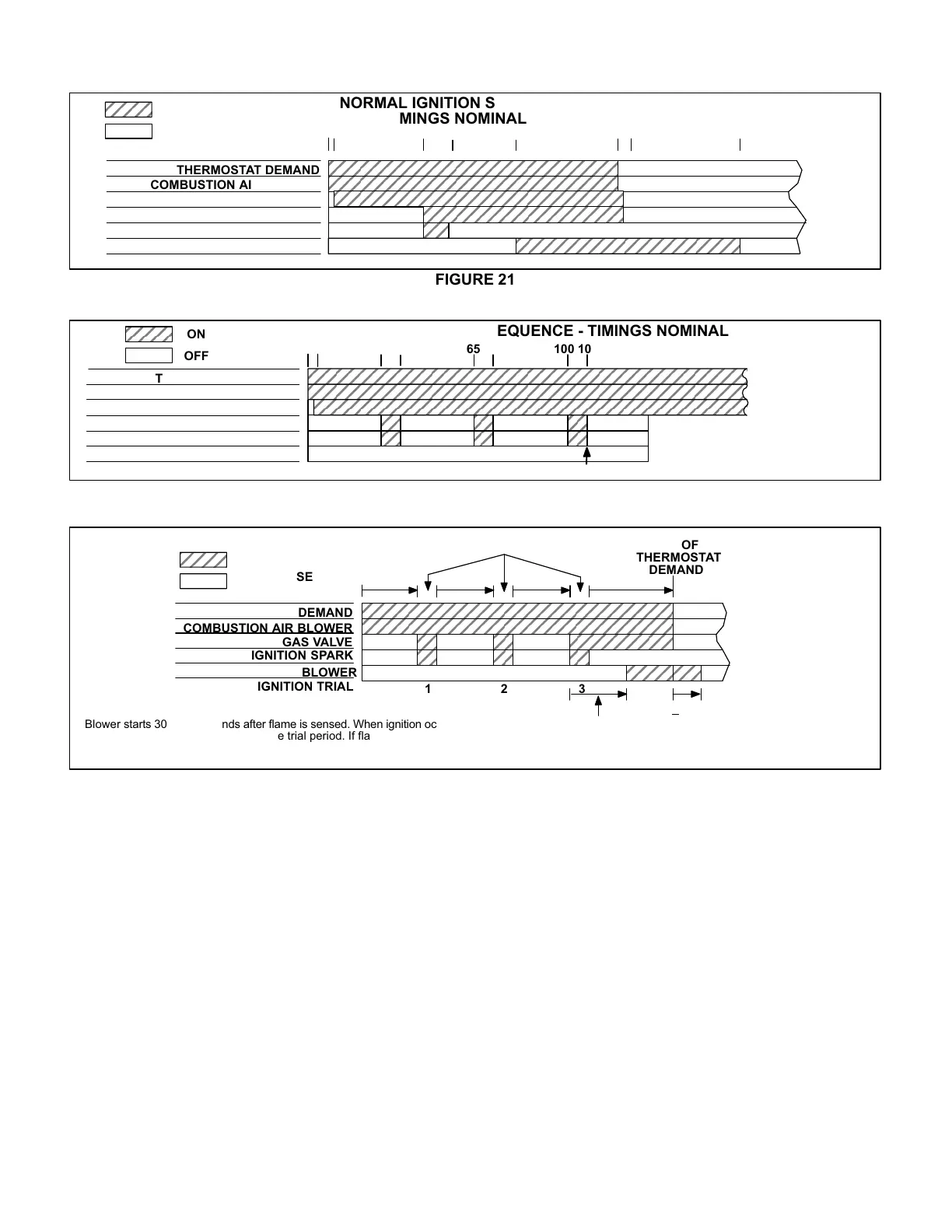
FIGURE 21
NORMAL IGNITION SEQUENCE
TIMINGS NOMINAL
THERMOSTAT DEMAND
COMBUSTION AIR BLOWER
GAS VALVE
IGNITION SPARK
BLOWER
IGNITION TRIAL
SECONDS 0 30 35 0 110
ON / CLOSED
OFF / OPEN
END OF
DEMAND
1
ÉÉÉÉÉÉÉÉÉÉÉÉÉ
ÉÉÉÉÉÉÉÉÉÉÉÉÉ
COMBUSTION AIR PROVE SWITCH
5 570
FIGURE 22
RETRIALS - IGNITION ATTEMPT SEQUENCE - TIMINGS NOMINAL
THERMOSTAT DEMAND
COMBUSTION AIR BLOWER
GAS VALVE
IGNITION SPARK
BLOWER
IGNITION TRIAL
SECONDS 0 30 35 70
ON
OFF
ÉÉÉÉÉÉÉÉÉÉÉÉÉÉÉÉÉÉÉÉ
ÉÉÉÉÉÉÉÉÉÉÉÉÉÉÉÉÉÉÉÉ
65 100 105
RESET AT THERMOSTAT
BY BREAKING DEMAND
FENWAL LOCKOUT
COMBUSTION AIR PROVE SWITCH
ÉÉÉÉÉÉÉÉÉÉÉÉÉÉÉÉÉÉÉ
ÉÉÉÉÉÉÉÉÉÉÉÉÉÉÉÉÉÉÉ
5
FIGURE 23
ÉÉÉÉÉÉÉÉÉÉÉÉÉÉ
ÉÉÉÉÉÉÉÉÉÉÉÉÉÉ
THERMOSTAT DEMAND
COMBUSTION AIR BLOWER
GAS VALVE
IGNITION SPARK
BLOWER
IGNITION TRIAL
SECONDS 0 30
ON
OFF
FENWAL - IGNITION CONTROL TIMING
30
30
HEATING
CYCLE
6.8 (+3.4, -2.0) SEC.
END OF
THERMOSTAT
DEMAND
12 3
Blower starts 30 to 45 seconds after flame is sensed. When ignition occurs on any trial, heating cycle begins. Ignition spark remains on for a total of 6.8 +3.4,
-2.0 seconds from the beginning of the trial period. If flame sensor detects loss of flame during heating cycle, gas valve remains open and ignition spark
begins for one second. If flame is detected before the end of one second, spark stops and the heating cycle continues. If flame is not detected during the
one second ignition retrial, the control cycles through the complete ignition sequence before locking out.
110+20 sec.
12-Heat Exchanger (Figure 15)
The GCS16 uses aluminized steel inshot burners with
matching tubular aluminized steel heat exchangers. Mod
els may be equipped with single or dual heat exchangers
depending on heating capacity. The second heat ex
changer in dual heat exchanger models is identical to the
first. Each heat exchanger uses multipletube/burner as
semblies controlled by a single two-stage gas valve. Each
burner uses a burner venturi to mix gas and air for proper
combustion. Combustion takes place at each tube en
trance. As hot combustion gases are drawn upward
through each tube by the combustion air blower, exhaust
gases are drawn out the top and fresh air/gas mixture is
drawn in at the bottom. Heat is transferred to the air stream
from all surfaces of the heat exchange tubes. The supply
air blower, controlled by the ignition control or the control
system (depending on which control system is installed),
forces air across all surfaces of the tubes to extract the
heat of combustion. The shape of the tubes and a deflector
ensure maximum heat exchange.
The gas valve accomplishes staging by allowing more or
less gas to the burners as called for by heating demand.
Single heat exchanger models accomplish staging by
cycling the second stage operator of the gas valve. When
thermostat demand calls for more heat, the second opera
tor of the gas valve opens to allow more gas to the burners.
Dual heat exchanger models are factory equipped to pro
vide two stages of heat in four increments. The first and
second stage operators of the first stage gas valve are
connected in parallel. The first stage operator of the gas
valve opens quickly but the second stage operator opens
 Loading...
