Page 31
slowly. On a heating call, the first stage operator opens im
mediately to begin first stage heating operation (first incre
ment). At the same time, the second stage operator begins
opening slowly (second increment). The second stage op
erator reaches full open after approximately 90 seconds.
The second heat exchanger is identical to the first heat ex
changer. The second heat exchanger operates in re
sponse to second stage (W2) demand. The first stage op
erator of the second gas valve (GV3W1) provides second
stage (third increment) heat and the second operator
opens slowly (fourth increment).
13-Burner Assembly (Figure 24)
The burners are controlled by the spark electrode, flame
sensing electrode, gas valve GV1 and combustion air blower.
The spark electrode, flame sensing electrode and gas valve
are directly controlled by the ignition control. The ignition con
trol is controlled by the combustion air blower. The combus
tion air blower is controlled by heating demand from the ther
mostat or control system.
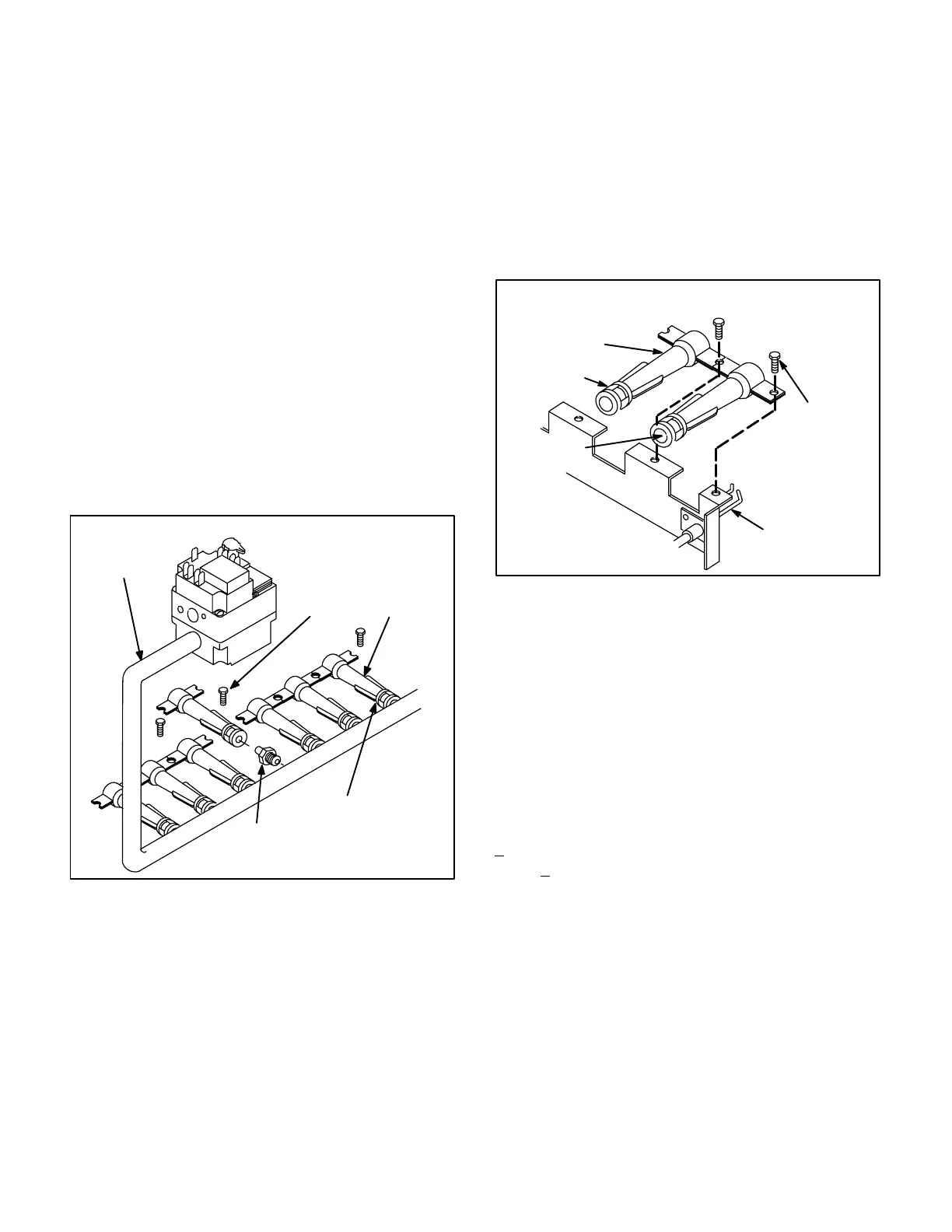
FIGURE 24
TYPICAL GAS MANIFOLD ASSEMBLY
GAS VALVE GV1
BURNERS
AIR SLOTS
BURNER
RETAINER
SCREW
MANIFOLD
ORIFICE
GAS VALVE POSITION
SLIGHTLY DIFFERENT
IN DUAL HEAT EX
CHANGER MODELS
a-Burners
All units use inshot burners (see figures 24 and 25 ).
Burners are factory set and do not require adjustment.
Burner air shutters are designed to be fully open only.
A peep hole with cover is furnished in the heating ac
cess panel for flame viewing. Always operate the unit
with the access panel in place. Burners can be re
moved individually for service. Burner maintenance
and service is detailed in the SERVICE CHECKS and
MAINTENANCE sections of this manual.
b-Orifice
Each burner uses an orifice which is precisely matched
to the burner input. The orifice is threaded into the burn
er manifold. The burner is supported by the orifice and
will easily slide off for service.
Each orifice and burner are sized specifically to the
unit. Refer to Lennox Repair Parts Listing for correct
sizing information.
TYPICAL BURNER AND ELEC
TRODE ASSEMBLY
BURNER
AIR SLOTS
ORIFICE
OPENING
ELECTRODE/
FLAME SENSOR
ASSEMBLY
SCREWS
FIGURE 25
D-Primary High Temperature Limit S10
S10 is the primary high temperature limit. It is located in
the heating compartment and is mounted to the lower por
tion of the panel dividing the heating compartment from
the blower compartment.
Primary limit S10 is wired in series with the ignition control.
Its N.C. contacts open to de-energize the ignition control
when excessive temperature is reached in the blower
compartment. The limit is a SPDT auto-reset switch. The
limit is factory preset to open its N.C. terminals at 165F
+6F on a temperature rise and automatically reset at
125F +7F on a temperature fall. The ignition circuit is im
mediately de-energized when terminals 1-3 open and
relay K20 is energized when terminals 1-2 close. This is a
primary safety shut-down function of the unit.
In dual heat exchanger models, both heat exchangers are
disabled when S10 opens. In fifteen ton and larger units,
the combustion air blower(s) continue to operate when
S10 opens.
E-Secondary High Temperature Limit S21
S21 is the secondary high temperature limit. It is also lo
cated in the heating compartment and is mounted to the
upper portion of the panel dividing the heating compart
ment from the blower compartment.
 Loading...
