Page 33
K-Combustion Air Motor Capacitor C3, C11
The Combustion air blower in all GCS16 units uses a
208/230V singlephase PSC ballbearing motor which re
quires a run capacitor. The capacitor is rated as shown in
Table 3. Capacitor C3 is connected to combustion air blow
er B6. In dual heat exchanger models, C11 is connected to
combustion air blower C11. C3 and C11 are identical.
L-Gas Valve GV1, GV3
GV1 and GV3 are gas valves used in GCS16 series units. All
units are equipped with gas valve GV1. Gas valve GV3 is
only used in units equipped with dual heat exchangers. GV3
is identical to to gas valve GV1 but is located in the second
stage heat exchanger.
Gas valve GV1 is a twostage redundant valve. Units may be
equipped with valves manufactured by either Honeywell or
White-Rodgers. First stage is quick opening (on and off less
than 3 seconds) Second stage is slow opening (on 1 minute,
off 1-1/2 minute) On a call for first stage heat, the valve is en
ergized by the ignition control simultaneously with the spark
electrode. On a call for second stage heat, the second stage
operator is energized after time delay DL3 closes. When de
mand is satisfied, second stage must be closed (1-1/2 min
utes to close completely) before 1st stage can close. A
manual shut-off knob is provided on the valve for shut-off.
Manual shutoff knob immediately closes both stages with
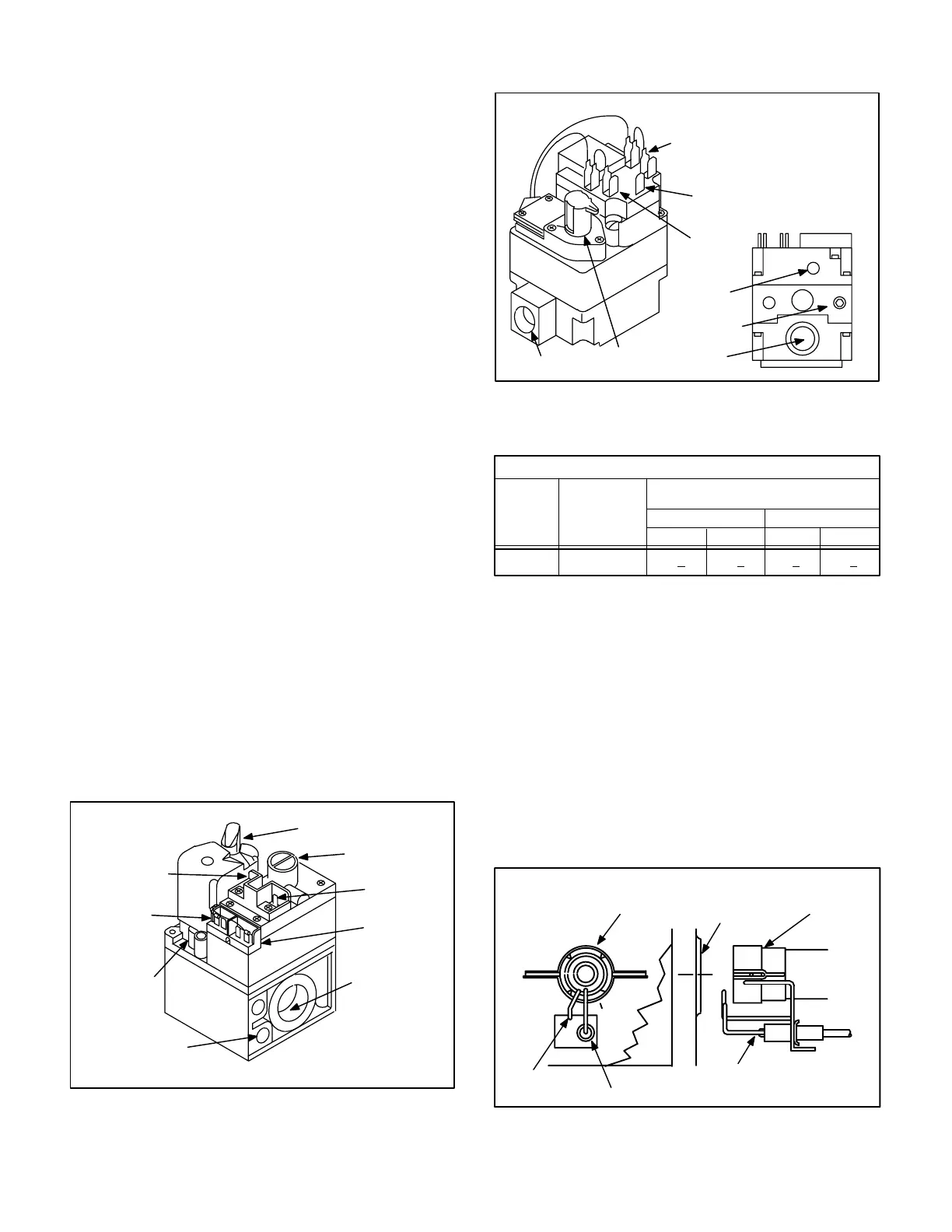
out delay. Figure 26 shows Honeywell gas valve compo
nents and figure 27 shows White-Rodgers gas valve compo
nents. Table 4 shows factory gas valve regulation for GCS16
series units.
FIGURE 26
HONEYWELL GAS VALVE GV1
PRESSURE
REGULATOR*
(under cap)
OUTLET
PRESSURE TAP
W1
TERMINAL
W1 COM.
TERMINAL
ON/OFF
KNOB
OUTLET
GROUND
TERMINAL
W2 COM.
TERMINAL
W2
TERMINAL
*Adjusts High Fire (2nd
Stage) Manifold Pressure
FIGURE 27
WHITE-RODGERS GAS VALVE GV1
W2
TERMINAL
COMMON
TERMINALS
ON/OFF
KNOB
INLET
W1
TERMINAL
OUTLET
OUTLET
PRESSURE
TAP
VENT
NOTE - VALVE IS
NOT EQUIPPED
WITH ADJUSTABLE
REGULATOR
TABLE 4
GAS VALVE REGULATION
Unit Input
K Btuh
Maximum
Inlet Pressure
in. W.C.
Operating Pressure
(outlet) in. W.C. Factory Setting
All Units
13.0
Natural* L.P.**
3.7+0.2
Low High Low High
1.6+0.1 10.5+0.55.5+0.3
* Adjustable Range 3.0 to 5.0 in. W.C. Honeywell Gas Valve only. White-Rodgers
gas valve is not adjustable.
** Field Installed Kit Adjustable Range 8.0 to 12.0 in. W.C.Honeywell Gas Valve
only. White-Rodgers gas valve is not adjustable.
M-Electrode Assembly
An electrode assembly is used for both ignition spark and
flame sensing. Two identical electrodes are used. Each
electrode is mounted at extreme ends of the burner sup
port. The electrodes are mounted through holes in the
burner support and the electrode tips protrude into the
flame envelope of the adjacent burner. The electrode on
the left acts as the flame ignitor and the electrode on the
right acts as the flame sensor. The electrode assembly is
fastened to burner supports and can be removed for ser
vice without removing any part of the burners.
SPARK ELECTRODE and FLAME SENSOR ASSEMBLY
FIGURE 28
ELECTRODE/SENSOR
GROUND
BURNER BURNER
HEAT EXCHANGER
ENTRANCE
ELECTRODE/SENSOR
 Loading...
