Page 34
During ignition spark travels through the spark (left) elec
trode and ignites the left burner. Flame travels from burner to
burner until all are lit. When flame is sensed by the right elec
trode (rightmost burner lit - indicated by microamp signal
through the flame) sparking stops. During operation, flame is
sensed by current passed along the ground electrode,
through the flame and into the sensing electrode. The igni
tion control allows the gas valve to stay open as long as a
flame signal (current passed through the flame) is sensed.
1-Spark Electrode
The spark electrode is connected to the ignition control
by a 5mm silicone insulated stranded high voltage
wire. The wire uses 1/4" female quick connect on the
electrode end and female spark plug-type terminal on
the ignition control end.
NOTE-IN ORDER TO MAXIMIZE SPARK ENERGY
TO ELECTRODE, HIGH VOLTAGE WIRE SHOULD
TOUCH UNIT CABINET AS LITTLE AS POSSIBLE.
2-Flame Sensor
Flame is sensed by rectification through the flame
sensing electrode.
N-Cooling Components
Summary of Features
Every GCS16-1853 uses three independent cooling circuits
consisting of three compressors, condenser coils and evap
orator coils. Vapor circuitry is shown in figure 31 and liquid
circuitry is shown in figure 32. Two draw-through type con
denser fans draw air across all three condenser coils during
all compressor operation. A single belt drive blower draws air
across all three evaporators during all unit operation. Cooling
may also be supplemented by fieldinstalled economizer.
The evaporators are slab type and are stacked as shown in
figure 35. Each evaporator uses a non-adjustable externally
equalized 5 ton expansion valve as the primary expansion
device. Each evaporator is also equipped with enhanced fins
and rifled tubing. The two condenser coils are split into three
independent circuits. Compressor 1 uses an independent
circuit in the right condenser coil (figure 31), compressor 2
uses an independent circuit in the left condenser coil and
compressor 3 uses an independent circuit split between the
left and right condenser coils. Each compressor is protected
by a crankcase heater, high pressure switch and loss of
charge switch. Additional protection is provided by factory
installed low ambient thermostat (unit control box) and free
zestats (on each evaporator). Each cooling circuit is
equipped with a thermometer well for charging.
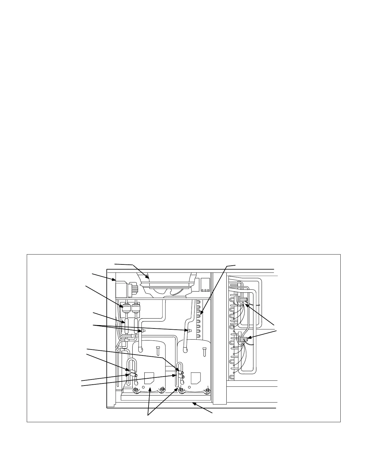
GCS16823, 953 PLUMBING COMPONENTS
FIGURE 29
FAN CONDENSER COILS
CONTROL BOX
DRIERS
THERMOMETER
WELLS and
LIQUID LINE
SERVICE PORTS
SUCTION LINE
SERVICE
PORTS
LOSS OF CHARGE
SWITCH (S24)
SWITCH (S25)
HIGH PRESSURE
LIMIT (S7)
LIMIT (S4)
COMPRESSOR
SERVICE ACCESS
OPENING
2ND STAGE
EVAPORATOR
1ST STAGE
EVAPORATOR
EXPANSION
VALVE
1ST STAGE2ND STAGE
 Loading...
