FIGURE 43
UNIT
Page 46
2- Remove lead from sensing electrode and install a
0-50DC microamp meter in series between the
sensing electrode and the sensing lead.
3- Reconnect power and adjust thermostat for heat
ing demand.
4- When flame is established, meter reading should be
8 to 20 microamps. Do not bend electrodes.
5- Disconnect power to unit before disconnecting
meter. Make sure sensor wire is securely recon
nected before reconnecting power to unit.
NOTE-If the meter scale reads 0, the leads are re
versed. Disconnect power and reconnect leads for
proper polarity.
M-Combustion Air Blower
The combustion air blower and prove switch are factory set
and are not field adjustable. However, operation should be
monitored to ensure proper operation. The combustion air
blower is used to draw fresh air into the combustion cham
ber while simultaneously expelling exhaust gases. The
blower operates throughout the heating cycle. On a heating
demand, the combustion air blower immediately energizes
but the ignition control circuit does not. Once the combus
tion air blower is energized, the combustion air prove switch
closes to energize the ignition control. The ignition control
then begins attempting ignition after 30-40 seconds.
If the combustion air blower does not reach full speed the
prove switch will not close and the ignition control will not
energize. The unit will remain locked out until the problem
is found and corrected.
VIII-INDOOR BLOWER
OPERATION / ADJUSTMENT
A-Blower Operation
NOTE-The following is a generalized procedure and
does not apply to all thermostat control systems.
1- Blower operation is dependent on the thermostat con
trol system option that has been installed in the
GCS16. Refer to the operation sequence for the con
trol system installed for detailed descriptions of blower
operation.
2- Generally, blower operation is set at the thermostat fan
switch. With the fan switch in ON" position, the blower
operates continuously. With the fan switch in AUTO"
position, the blower cycles with demand (or, with some
control systems, runs continuously while the heating or
cooling circuits cycle).
3- In most cases, the blower and entire unit will be off
when the system switch is in the OFF" position. The
only exception is immediately after a heating demand
until blower control switches off.
B-Determining Unit CFM
1- The following measurements must be made with a dry
indoor coil. Run the blower without the cooling de
mand. Air filters must be in place when measurements
are taken.
2- Measure static pressure external to the unit (from sup
ply to return).
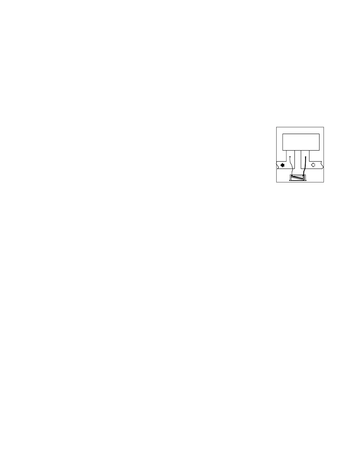
To Measure Discharge Static Pressure:
a- Locate taps as shown in figure 43.
b- Punch a 1/4" diameter hole. Insert manometer hose
flush with the inside edge of hole or insulation. Seal
around the hole with per
magum. Connect the
zero end of the manome
ter to the discharge (sup
ply) side of the system.
Connect the other end of
the manometer to the re
turn duct as above.
c- With only the blower motor running, observe ma
nometer reading.
d- Seal around the hole when the check is complete.
3- Measure indoor blower wheel RPM (figure 44).
4- Refer to unit nameplate to determine the blower motor
horsepower.
5- Use the static pressure and RPM readings to deter
mine unit CFM.
6- The CFM can be adjusted at the motor pulley (see
section C-Blower Belt Adjustment).
Determining Unit CFM (Alternative Method):
Air volume may also be determined by measuring pres
sure drop across the indoor coil.
1- Remove lifting lug bolt located on the blower side of
unit above condensate drain. Use an awl or screw
driver to open a hole in the insulation.
2- Insert the positive or high pressure hose of draft
gauge 1 inch past the insulation.
3- Remove filter access panel and insert other hose through
hole provided on the panel above filter and connect to
negative (low) pressure side of gauge.
4- Turn on blower and determine draft gauge reading.
5- Adjust blower speed as required (see section C-Blow
er Belt Adjustment).
C-Blower Belt Adjustment
Proper pulley alignment and belt tension must be main
tained for maximum belt life.
NOTE-Tension new belt after 24-48 hours of operation.
This will allow belts to stretch and seat in grooves. To
increase belt tension, loosen two locking bolts and pull
mounting plate. Tighten motor mounting plate in verti
cal position.
 Loading...
