Page 45
6- Turn on power to unit. Follow lighting instructions
attached to unit and operate unit in heating mode.
Check burner flames. They should be blue with
yellow streaks.
NOTE-If the unit is operated with the heating access
panel off and burners cold, the burner sound will in
creased due to cold, dense primary air. This is normal
and will subside as the heat exchanger warms up during
operation. The sound will be even further reduced with
the access panel in place.
I-Heat Exchanger
To Access or Remove Heat Exchanger From Unit:
1- Turn off gas and electric power.
2- Remove access panel and unit end panel.
3- Remove gas valve, manifold assembly and burn
ers.
4- Remove combustion air blower and flue box. Pay
careful attention to the order in which gaskets and
orifice are removed.
5- Support heat exchanger (to prevent it from falling
when final bolts are removed.)
6- Remove bolts supporting heat exchanger.
7- To install heat exchanger, reverse procedure. Be
sure to secure all wires and check plumbing and
burner plate for airtight seal. Bolts must be torqued
to 35 inlbs. to ensure proper operation.
J-Ignition (Burner) Control A3
Ignition control A3 is factory set and is not adjustable. The
control makes three attempts at ignition and then locks out
the system if ignition is not obtained after the third trial. Re
set after lockout requires only breaking and remaking ther
mostat demand. The control shuts off gas flow immediate
ly in the event of a gas or power failure. Upon restoration of
gas and power, the control will restart the ignition se
quence and continue until flame is established or system
locks out.
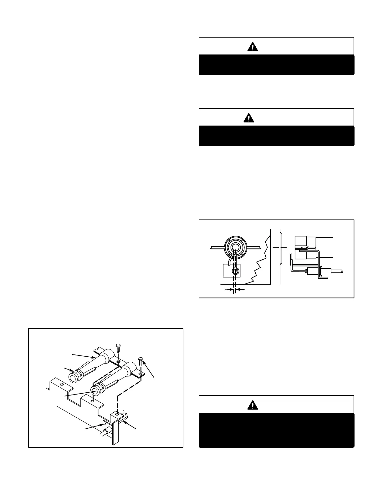
FIGURE 41
BURNER REMOVAL AND
ELECTRODE/SENSOR ORIENTATION
BURNER
AIR SLOTS
ORIFICE
OPENING
ELECTRODE/
FLAME SENSOR
ASSEMBLY
REMOVE SCREWS
TO REMOVE
ELECTRODE/SENSOR
REMOVE
SCREW
TO REMOVE
BURNERS
DANGER
Shock hazard. Spark related components contain
high voltage. Disconnect power before servicing.
For proper unit operation, the electrodes must be posi
tioned correctly in the flame and must be gapped cor
rectly.
WARNING
The ignition control is not field repairable. Unsafe
operation will result.
K-Spark Electrode/Flame Sensor Gap
The electrode assembly can be removed for inspection by
removing two screws securing the electrode assembly
and sliding it out of unit.
Spark gap may be checked with appropriately sized twist
drills or feeler gauges. Disconnect power to the unit and
remove electrode assembly. The gap should be between
0.094" and 0.156". See figure 42.
SPARK ELECTRODE and FLAME SENSOR GAP
FIGURE 42
1/8" + 1/32"
SENSOR/ELECTRODE GAP
L-Flame Sensing
Flame current is an electrical current which passes from the
ignition control through the sensor electrode during unit op
eration. The current passes from the sensor through the
flame to ground electrode to complete a safety circuit. The
minimum flame current necessary to keep the ignitor from
lockout is 5 microamps. The electrodes should be located so
the tips are at least 1/2" inside the flame envelope. Do not
bend electrodes. To measure flame current, follow the pro
cedure below:
DANGER
Electrodes are not field adjustable. Any alter
ations to the electrode may create a hazardous
condition that can cause property damage or per
sonal injury.
1- Disconnect power to unit.
 Loading...
