A11
COIL COIL COIL COIL COIL
GW1W2Y2Y1
K46 K77 K49 K67 K66
CC CCC
GND
NO NO NO NO NO NCNCNCNCNC
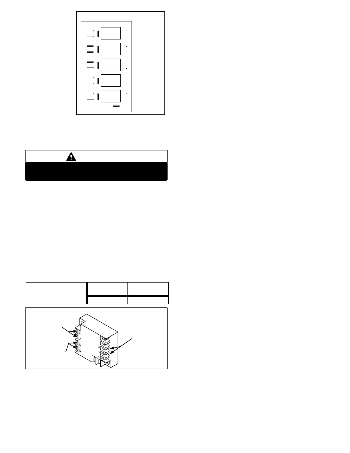
PILOT RELAY BOARD A11
BLOWER
PILOT
1st STAGE
HEATPILOT
2nd STAGE
HEAT PILOT
2nd STAGE
COOL PILOT
1st STAGE
COOL PILOT
FIGURE 13
Page 25
could potentially
cause voltage
drop resulting in
contactor chatter
ing. The pilot re
lays are added be
tween the thermo
stat and the con
tactors (refer to
unit wiring dia
gram) to electri
cally isolate the
contactor coils
from the thermostat wire and thereby minimize the poten
tial for voltage drop at the contactors.
WARNING
Do not remove or bypass the pilot relay board.
Control damage or failure could reult.
20-Compressor Motor Protector A9, A10
(2553, 2753, 3003 only) 575 Volt Only
Motor protectors A9 and A10 are used in all GCS16 18.5
ton and larger units to provide compressor overtempera
ture sensing which helps protect the compressors. Com
pressors in these units have thermistors imbedded in the
motor windings. The motor protectors monitor the sensors
in each compressor and shuts off the compressor when
resistance increases above a preset limit. As the compres
sor windings cool, the resistance through the sensors
drops and the control resets. Table 2 shows the resistance
values for the winding temperature sensors.
TABLE 2
Compressor Winding
Trip Ohms
Temp. Rise
Reset Ohms
Tem. Fall
Temperature Sensor
16K to 24K 5.5K to 6.9K
FIGURE 14
COMPRESSOR PROTECTOR A9, A10
TO
COMPRESSOR
SENSORS
24VAC
POWER
IN SERIES WITH
CONTACTOR COIL
21- Low Ambient Lockout Switch
(Compressor Monitor) S3 (all units)
GCS16 units are equipped with a single compressor moni
tor located in the unit control box. The compressor monitor
is a SPST bimetal thermostat which opens on a tempera
ture drop. It is connected inline with the 24VAC compres
sor control circuits. When outdoor temperature drops be
low 40°F the compressor monitor opens to electrically dis
connect all compressors. When the compressors are dis
connected, cooling demand is handled by optional
REMD16 economizer (if installed). The monitor automati
cally resets when outdoor temperature rises above 50°F.
NOTE-Compressor monitors must be disconnected if
optional low ambient kit is used.
22- Low Ambient Lockout Switch
(Compressor Monitor) S30
(1353, 1603 only)
CHA161353 and 1603 (10 and 12.5 ton) units are
equipped with a second compressor monitor (S30) used in
addition to compressor monitor S3. S3 is identical to S30.
In units equipped with two compressor monitors, S3 pro
tects the first stage compressors and S30 protects the
second stage compressors.
23-Compressor Delay DL15
(1603 Y voltage, 1853 all voltages)
Time delay DL15 is a SPST N.O. timedelay switch. Once
energized, the delay waits 30 seconds + 3 seconds before
closing. The purpose of the delay is to prevent voltage
drop at the contactor coil due to (the possibility of) multiple
contactors being energized at the same time. With the
delay added, only two contactors (K1 and K10) can ener
gize at the same time while the third contactor (K2) must
wait 30 seconds before energizing. When thermostat de
mand stops, DL15 immediately opens and resets.
In both units, the delay is wired in series with compressor
contactor coil (K2). In GCS161603 units, the delay is en
ergized upon receiving a call for second stage cooling. In
CHA161853 units the delay is energized simultaneously
with compressor 1 contactor K1 and condenser outdoor
fan contactor K10.
In GCS161853 units, once contactor K2 is energized, a
set of N.O. K2-2 auxiliary contacts close to bypass the
time delay (wired in parallel with time delay DL15). When
K2-2 closes, the resulting shunt eliminates the load add
ed by the time delay (allows K2 to receive full voltage).
 Loading...
