Page 22
System Operation
UNIT COMPONENTS
IMPORTANT
Some scroll compressors have an internal vacuum
protector that will unload scrolls when suction pressure
goes below 20 psig. A hissing sound will be heard when
the compressor is running unloaded. Protector will
reset when low pressure in system rises above 40 psig.
DO NOT REPLACE COMPRESSOR.
The outdoor unit and indoor blower cycle on demand from
the room thermostat. If the thermostat blower switch is in
the ON position, the indoor blower operates continuously.
Bi-Flow Liquid line Filter Drier
The unit is equipped with a large-capacity bi-ow lter dri-
er which keeps the system clean and dry. If replacement is
necessary, order another of the same design and capac-
ity. The replacement lter drier must be suitable for use
with HFC-410A refrigerant.
High Pressure Switch (S4)
This unit is equipped with a high pressure switch which is
located on the liquid line. The SPST, normally closed pres-
sure switch opens when liquid line pressure rises above
the factory setting of 590 + 15 psig and automatically re-
sets at 418 + 15 psig.
If the high pressure switch opens 5 times during a single
thermostat demand, the defrost control will lock out the
compressor.
Low Pressure Switch (S87)
This unit is equipped with a low pressure switch which is
located on the suction line. The SPST, normally closed
pressure switch opens when the suction pressure drops
below the factory setting of 25 PSIG +/- 5 PSIG and auto-
matically resets at 40 PSIG +/- 5 PSIG. If the low pressure
switch opens 5 times during a single thermostat demand,
the defrost control will lock out the compressor. The de-
frost control has an on-board thermistor and will ignore the
pressure switch when the outdoor temperature is below
approximately 15 degrees F.
Resetting Defrost Control High and Low Pressure
Switch Lockout
The defrost control will lock out the compressor if the
high or low pressure switch opens 5 times during a single
thermostat demand. To reset a 5-strike pressure switch
lockout, cycle 24V control power to the defrost control or
place the defrost control in the “TEST” mode by shorting
the “TEST” pins for 2 seconds.
Defrost Thermostat (S6)
The defrost thermostat is located on the liquid line be-
tween the check/expansion valve and the distributor.
When defrost thermostat senses 42°F (5.5°C) or cooler,
the thermostat contacts close and send a signal to the
defrost control to start the defrost timing. It also terminates
defrost when the liquid line warms up to 70°F (21°C).
Crankcase Heater (HR1) and Thermostat Switch (S40)
Certain models are equipped with a belly band type crank-
case heater. HR1 prevents liquid from accumulating in the
compressor. The HR1 is controlled by a single pole, single
throw thermostat switch (S40) located on the liquid line.
On all units, the heater is on when there is no compressor
operation.
Thermal Protection Switch (S173) – Compressor
Mounted
Some ML14XP1 units are equipped with a compressor
mounted normally closed temperature switch that pre-
vents compressor damage due to overheating caused by
internal friction. The switch is located on top of the com-
pressor casing (see gure 1).
This switch senses the compressor casing temperature
and opens at 239-257°F (115°C-125°C) to shut o com-
pressor operation. The auto-reset switch closes when
the compressor casing temperature falls to 151-187°F
(66°C-86°C), and the compressor is re-energized. This
single-pole, single-throw (SPST) bi-metallic switch is
wired in series with the 24V Y input signal to control com-
pressor operation.
System Conguration
The defrost system includes a defrost thermostat (S6) and
a defrost control (CMC1).
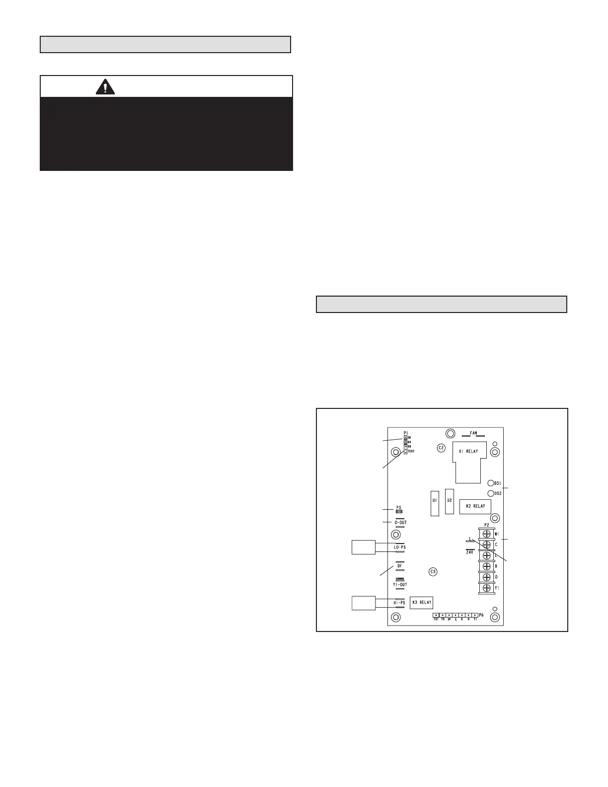
DEFROST CONTROL (CMC1)
This defrost control includes the combined functions of a
time/temperature defrost control, defrost relay, time delay,
diagnostic LEDs and a terminal strip for eld wiring con-
nections.
24V TERMINAL
STRIP
CONNECTIONS
DIAGNOSTIC
LEDS
HIGH PRESSURE
TEST
PINS
DEFROST TIMING
PINS (P1)
REVERSING
VALVE
DEFROST
THERMOSTAT (S6)
LOW PRESSURE
SWITCH
COMPRESSOR
DELAY PINS
S4
S87
SERVICE LIGHT
CONNECTIONS
FIGURE 14
The defrost control provides automatic switching from nor-
mal heating operation to defrost mode and back. When
the defrost thermostat is closed, the control accumulates
compressor run time at 30-, 60- or 90- minute eld-adjust-
able intervals.
When the selected compressor run time interval is
reached, the defrost relay is energized and defrost begins.
 Loading...
