Page 17
Approach Method and
Normal Operating Pressures
TXV Systems – Outdoor Temp. >
65F (18C)
The following procedure is intended as a general guide and
is for use on expansion valve systems only. For best results,
indoor temperature should be 70°F (21°C) to 80°F (26°C).
Monitor system pressures while charging.
1 − Record outdoor ambient temperature using a digital
thermometer.
2 − Attach high pressure gauge set and operate unit for
several minutes to allow system pressures to stabilize.
3 − Compare stabilized pressures with those provided in
table 8, Normal Operating Pressures." Minor varia-
tions in these pressures may be expected due to differ-
ences in installations. Significant differences could
mean that the system is not properly charged or that a
problem exists with some component in the system.
Pressures higher than those listed indicate that the
system is overcharged. Pressures lower than those
listed indicate that the system is undercharged. Verify
adjusted charge using the approach method.
Approach Method
4 − Use the same digital thermometer you used to check
the outdoor ambient temperature to check the liquid
line temperature.
5 − The difference between the ambient and liquid temper-
atures should match values given in table 7. If the val-
ues don’t agree with the those in table 7, add refriger-
ant to lower the approach temperature, or recover re-
frigerant from the system to increase the approach
temperature.
Be aware of the R410A refrigerant cylinder. It will be
rose−colored. Refrigerant should be added through the
vapor valve in the liquid state. Some R410A cylinders
are equipped with a dip tube which allows you to
draw liquid refrigerant from the bottom of the cylin-
der without turning the cylinder upside−down. The
cylinder will be marked if it is equipped with a dip
tube.
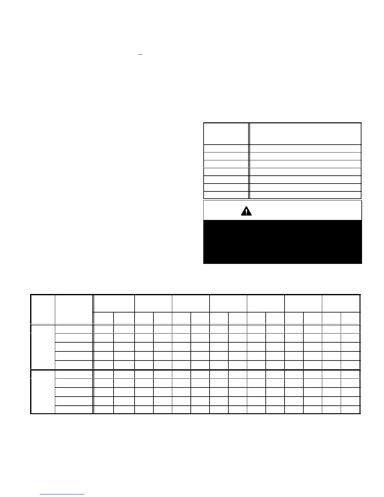
Table 7
HSXA12 Approach Values
Model No.
Approach Temperature
Liquid Line −
Outdoor Ambient °F (°C)
−018 10 (5.6)
−024 12 (6.7)
−030 13 (7.2)
−036 12 (6.7)
−042 11 (6.1)
−048 13 (7.2)
−060 14 (7.8)
IMPORTANT
Use table 8 to perform maintenance checks. Table 8
is not a procedure for charging the system. Minor
variations in these pressures may be due to differ-
ences in installations. Significant deviations could
mean that the system is not properly charged or that
a problem exists with some component in the system.
Table 8
Normal Operating Pressures In psig (liquid +/− 10 and vapor +/− 5 PSIG)*
Mode
Out. Coil
Entering Air
−018 −024 −030 −036 −042 −048 −060
Temp.
°F (°C)
LIQ SUC LIQ SUC LIQ SUC LIQ SUC LIQ SUC LIQ SUC LIQ SUC
65 (18.3) 238 123 261 131 261 128 268 130 254 121 270 124 280 121
75 (23.9) 275 131 300 135 300 133 308 134 296 128 311 130 332 126
fixed
85 (29.4) 317 136 343 139 343 138 351 138 340 133 356 134 379 130
orifice
95 (35.0) 362 141 391 143 387 141 398 142 389 138 404 139 427 135
105 (40.6) 410 144 441 147 434 145 447 146 440 142 456 143 479 140
65 (18.3) 234 133 256 134 256 137 264 135 256 124 269 131 262 121
75 (23.9) 270 135 298 137 296 139 305 138 296 127 312 133 304 127
TXV
85 (29.4) 312 137 344 140 339 141 349 139 341 133 357 135 349 132
95 (35.0) 361 138 394 142 384 144 396 140 389 136 406 137 397 136
105 (40.6) 409 141 448 143 432 146 446 143 440 140 460 140 449 140
*These are typical pressures only. Indoor indoor match up, indoor air quality, and indoor load will cause the pressures
to vary.
 Loading...