Page 5
Refrigerant Piping
If the HSXA12 unit is being installed with an indoor coil and
line set, make the refrigerant connections as outlined in this
section. If an existing line set and/or indoor coil is going to
be used to complete the HSXA12 system, refer to this sec-
tion, as well as the flushing section which follows.
Field refrigerant piping consists of liquid and vapor lines
from the outdoor unit (sweat connections) to the indoor coil
(flare or sweat connections). Use Lennox L15 (sweat, non-
flare) series line sets as shown in table 1 or use field-fabri-
cated refrigerant lines. Refer to Refrigerant Piping Guide
(Corp. 9351−L9) for proper size, type, and application of
field−fabricated lines. Valve sizes are also listed in table 1.
Refrigerant Line Connections
HSXA12 Matched with New Indoor Coil and Line Set
If the HSXA12 is being used with an existing indoor coil
which was equipped with a liquid line which served as
a metering device (RFCI), the liquid line must be re-
placed prior to the installation of the HSXA12 unit.
If refrigerant lines are routed through a wall, seal and isolate
the opening so vibration is not transmitted to the building.
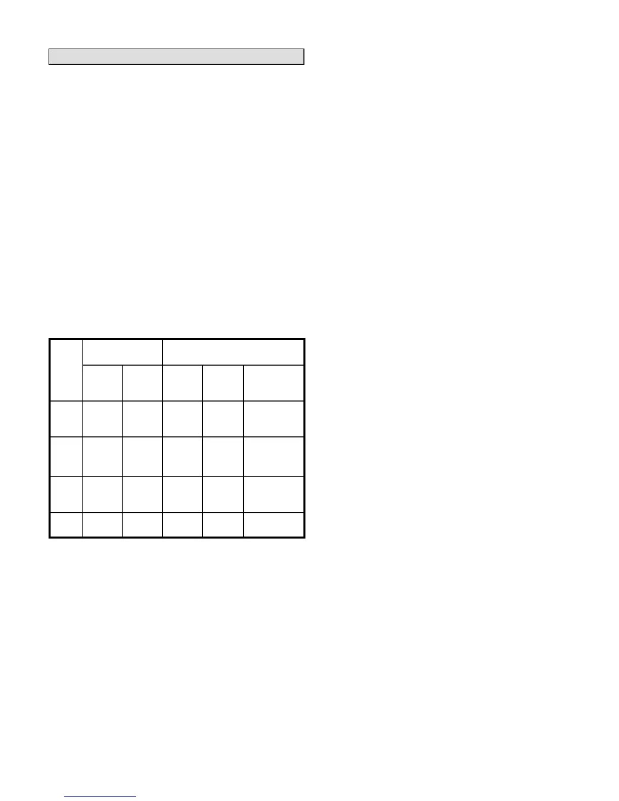
Table 1
Refrigerant Line Sets
Valve Field Size
Connections
Recommended Line Set
Model
Liquid
Line
Vapor
Line
Liquid
Line
Vapor
Line
L15
Line Sets
−018
3/8 in.
(10 mm)
5/8 in.
(16 mm)
3/8 in.
(10 mm)
5/8 in.
(19 mm)
L15−26
15 ft. − 50 ft.
(4.6 m − 15 m)
024
−030
−036
3/8 in.
(10 mm)
3/4 in.
(19 mm)
3/8 in.
(10 mm)
3/4 in.
(19 mm)
L15−41
15 ft. − 50 ft.
(4.6 m − 15 m)
−042
−048
3/8 in.
(10 mm)
7/8 in.
(22 mm)
3/8 in.
(10 mm)
7/8 in.
(22 mm)
L15−65
15 ft. − 50 ft.
(4.6 m − 15 m)
−060
3/8 in.
(10 mm)
1−1/8 in.
(29 mm)
3/8 in.
(10 mm)
1−1/8 in.
(29 mm)
Field
Fabricated
NOTE − Units are designed for line sets of up to fifty feet (15
m). For applications longer than fifty feet, consult the Len-
nox Refrigerant Piping Guide (Corp. 9351−L9). Select line
set diameters from table 1 to ensure that oil returns to the
compressor.
Installing Refrigerant Line
During the installation of any heat pump or a/c system, it is
important to properly isolate the refrigerant lines to prevent
unnecessary vibration. Line set contact with the structure
(wall, ceiling or floor) causes some objectionable noise
when vibration is translated into sound. As a result, more
energy or vibration can be expected. Closer attention to
line set isolation must be observed.
Following are some points to consider when placing and
installing a high−efficiency outdoor unit:
1- Placement − Be aware some localities are adopting
sound ordinances based on how noisy the unit is from
the adjacent property not at the original installation.
Install the unit as far as possible from the property line.
When possible, do not install the unit directly outside a
window. Glass has a very high level of sound transmis-
sion.
2- Line Set Isolation − The following illustrations demon-
strate procedures which ensure proper refrigerant line
set isolation. Figure 5 shows how to install line sets on
vertical runs. Figure 6 shows how to install line sets on
horizontal runs. Figure 7 shows how to make a transition
from horizontal to vertical. Finally, figure 8 shows how to
place the outdoor unit and line set.
 Loading...