EasyManua.ls Logo

Lennox KGB024 User Manual

Lennox KGB024
56 pages
To Next Page IconTo Next Page
Page #1 background imageLoading...
Page #1 background image
©2015
Litho U.S.A.
WARNING
Improper installation, adjustment, alteration, ser
vice or maintenance can cause property damage,
personal injury or loss of life. Installation and ser
vice must be performed by a licensed professional
HVAC installer or equivalent, service agency, or the
gas supplier
Table Of Contents
Dimensions Page 2.................................
Parts Arrangements Page 3.........................
Shipping and Packing List Page 4....................
General Page 4....................................
Requirements Page 4...............................
Unit Support Page 5................................
Duct Connection Page 5............................
Rigging Unit For Lifting Page 6.......................
Horizontal Air Discharge Page 6......................
Condensate Drains Page 6..........................
Gas Piping Page 8.................................
Pressure Test Gas Piping Page 9.....................
High Altitude Derate Page 9.........................
Electrical Connections Page 9.......................
Blower Operation and Adjustments Page 11............
Cooling Start-Up Page 42............................
Gas Heat Start-Up Page 51...........................
Heating Operation and Adjustments Page 52............
Electric Heat Start-Up Page 52........................
Service Page 53....................................
INSTALLATION
INSTRUCTIONS
KGB/KCB024
KGB/KCB030
KGA/KCA036
KGB/KCB036
KGA/KCA048
KGB/KCB048
KGA/KCA060
KGB/KCB060
KGA/KCA072
KGB/KCB072
KGB/KCB074
KGA/KCA090
2-Ton
2-1/2-Ton
3-Ton
3-Ton
4-Ton
4-Ton
5-Ton
5-Ton
6-Ton
6-Ton
6-Ton
6-Ton
7-1/2 Ton
GAS AND COOLING PACKAGED UNITS
507348-04
12/2015
Supersedes 507348-01, -02, -03
RETAIN THESE INSTRUCTIONS FOR FUTURE REFERENCE
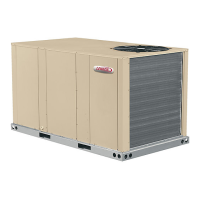
KG SHOWN

Table of Contents

Question and Answer IconNeed help?

Do you have a question about the Lennox KGB024 and is the answer not in the manual?

Lennox KGB024 Specifications

General IconGeneral
Tonnage2
BTU24000
Refrigerant TypeR-410A
Operating Voltage208/230 V
Phase1
Sound Level (Outdoor Unit)76 dB
Cooling Capacity24000 BTU/hr
SEER Rating13 SEER

Summary

DIMENSIONS

PARTS ARRANGEMENT

Shipping and Packing List

General

Requirements

Unit Support

A-Downflow Discharge Application

Details for downflow discharge installation, including roof mounting.

B-Horizontal Discharge Applications

Guidance for horizontal discharge applications, including clearances.

Duct Connection

Rigging Unit For Lifting

Horizontal Air Discharge

Condensate Drains

Bottom Drain Connection

Connect Gas Piping (Gas Units)

Pressure Test Gas Piping (Gas Units)

High Altitude Derate

Electrical Connections

POWER SUPPLY

Details on connecting the electrical power supply to the unit.

CONTROL WIRING

A-Thermostat Location

Guidance on selecting an optimal location for the room thermostat.

B-Control Wiring

Instructions for routing and connecting thermostat and control wiring.

Blower Operation and Adjustments

A-Blower Operation

Steps for initiating blower operation based on thermostat demand.

B-Determining Unit CFM - Direct Drive Blowers

Procedure to determine CFM for direct drive blowers using static pressure.

C-Determining Unit CFM - Belt Drive Blowers

D-Blower Belt Adjustment

E-Blower Belt Adjustment - M Volt Units With 3 HP Blowers Equipped With A Belt Tensioner

F-Check Belt Tension - Units Not Equipped With A Belt Tensioner

G-Field-Furnished Blower Drives

BLOWER DATA

BELT DRIVE KIT SPECIFICATIONS

Specifications for belt drive kits, including motor and blower choices.

OPTIONS / ACCESSORIES AIR RESISTANCE FOR 024-074 MODELS

Air resistance values for various options and accessories on specific models.

OPTIONS / ACCESSORIES AIR RESISTANCE FOR 090 MODELS

Air resistance values for options and accessories on the 090 model.

POWER EXHAUST FAN PERFORMANCE

Performance data for the power exhaust fan.

Cooling Start-Up

A-Operation

Steps to initiate cooling demands and unit operation.

B-Three Phase Scroll Compressor Voltage Phasing

Ensuring correct compressor and blower rotation for three-phase units.

F-Compressor Controls

1- Freezestat (S49)

Function of the freezestat switch to prevent evaporator freeze-up.

2- High Pressure Switch (S4)

Operation of the high pressure switch for system protection.

3- Compressor High Temperature Limit (S5)

Role of the high temperature limit switch for compressor protection.

Gas Heat Start-Up (Gas Units)

A-Placing Unit In Operation

Steps to place the unit in operation and light the burner safely.

Gas Valve Operation (figure 24 and 25)

Description of the gas valve operation and settings.

Heating Operation and Adjustments (Gas Units)

A-Heating Sequence of Operation

Sequence of events during heating demand and ignition.

B-Ignition Control Diagnostic LED's

Interpreting LED status for ignition control diagnostics.

C-Limit Controls

Information on factory-set limit controls for heating operation.

D-Heating Adjustment

Details on manifold pressures for gas burners.

Electric Heat Start-Up (KC Units)

Service

A-Filters

C-Burners (Gas Units)

D-Combustion Air Inducer (Gas Units)

E-Flue Box (Gas Units)

F-Evaporator Coil

G-Condenser Coil

All-Aluminum Coils

Cleaning instructions for all-aluminum condenser coils.

Fin/Tube Coils

Cleaning procedures for fin/tube condenser coils.

H-Compressor

J-Supply Air Blower Wheel

J-Supply Air Blower Replacement

Related product manuals