Page 31
GROUND
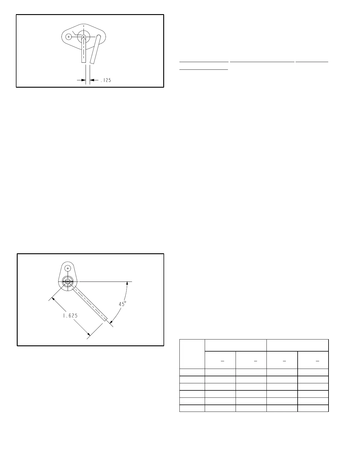
ELECTRODE
FIGURE 25
IGNITOR
11-Flame Sensors
A flame sensor is located on the right side of each burner
support. The sensor is mounted through a hole in the
burner support and the tip protrudes into the flame
envelope of the right most burner. The sensor assembly is
fastened to burner supports and can be removed for
service without removing any part of the burners.
When flame is sensed by the flame sensor (indicated by
microamp signal through the flame) sparking stops
immediately. During operation, flame is sensed by current
passed along the ground electrode (located on the spark
electrode), through the flame and into the sensing
electrode. The ignition control allows the gas valve to stay
open as long as a flame signal (current passed through the
flame) is sensed.
SENSOR
FIGURE 26
II-PLACEMENT AND INSTALLATION
Make sure the unit is installed in accordance with the
installation instructions and all applicable codes. See
accessories section for conditions requiring use of the
optional roof mounting frame.
III-CHARGING
A-Refrigerant Charge and Check - Fin/Tube Coil
WARNING-Do not exceed nameplate charge under any condition.
This unit is factory charged and should require no further
adjustment. If the system requires additional refrigerant,
reclaim the charge,
evacuate the system and add required
nameplate charge.
NOTE - System charging is not recommended below 60°F
(15°C). In temperatures below 60°F (15°C), the charge
must be weighed into the system.
If weighing facilities are not available, or to check the
charge, use the following procedure:
IMPORTANT - Charge unit in normal cooling mode.
1- Attach gauge manifolds to discharge and suction lines.
With the economizer disabled, operate the unit in
cooling mode at high speed using the following
mobile service app menu path:
SERVICE>TEST>COOL>COOL 3
2- Use a thermometer to accurately measure the outdoor
ambient temperature.
3- Apply the outdoor temperature to tables 8 to 10 to
determine normal operating pressures.
Pressures are
listed for sea level applications at 80°F dry bulb and
67°F wet bulb return air.
4- Compare the normal operating pressures to the
pressures obtained from the gauges. Minor variations
in these pressures may be expected due to differences
in installations. Significant differences could mean that
the system is not properly charged or that a problem
exists with some component in the system. Correct
any system problems before proceeding.
5- If discharge pressure is high, remove refrigerant from
the system. If discharge pressure is low, add
refrigerant to the system.
S Add or remove charge in increments.
S Allow the system to stabilize each time
refrigerant is added or removed.
6- Use the following approach method along with the
normal operating pressures to confirm readings.
TABLE 8
156 Compressor 1 Frequency 56Hz - 581167-01
Outdoor
Coil En
tering
Air
Temp
Circuit 1 Circuit 2
Dis. +10
psig
Suc. +5
psig
Dis. +10
psig
Suc. +5
psig
65°F 218 110 232 118
75°F 262 129 279 138
85°F 305 146 319 144
95°F 350 149 365 148
105°F 400 152 416 150
115°F 454 155 471 153
 Loading...
