EasyManua.ls Logo

Lennox LDT DUAL FUEL Series User Manual

Lennox LDT DUAL FUEL Series
50 pages
To Next Page IconTo Next Page
Page #1 background imageLoading...
Page #1 background image
Page 1
UNIT INFORMATIONUNIT INFORMATION
Service Literature
WARNING
Improper installation, adjustment, alteration,
service or maintenance can cause property damage,
personal injury or loss of life. Installation and service
must be performed by a licensed professional HVAC
installer or equivalent, service agency, or the gas
supplier
CAUTION
As with any mechanical equipment, contact with
sharp sheet metal edges can result in personal
injury. Take care while handling this equipment and
wear gloves and protective clothing.
Table of Contents
Options / Accessories . . . . . . . . . . . . . . . . . . . . . Page 2

Blower Tables . . . . . . . . . . . . . . . . . . . . . . . . . . . Page 8
Electrical Data . . . . . . . . . . . . . . . . . . . . . . . . . . Page 11
I-Unit Components . . . . . . . . . . . . . . . . . . . . . . . Page 14
II-Placement and Installation . . . . . . . . . . . . . . . Page 27
III-Start Up . . . . . . . . . . . . . . . . . . . . . . . . . . . . . . Page 27
IV-System Service Checks. . . . . . . . . . . . . . . . . . . . Page 30
V-Maintenance . . . . . . . . . . . . . . . . . . . . . . . . . . Page 33
VI-Accessories . . . . . . . . . . . . . . . . . . . . . . .Page 34
VII-Wiring and Operation Sequence . . . . . . . . . . Page 39
WARNING
To prevent serious injury or death:
1- Lock-out/tag-out before performing maintenance.
2- If system power is required (e.g., smoke detector
maintenance), disable power to blower, remove
fan belt where applicable, and ensure all
controllers and thermostats are set to the “OFF”
position before performing maintenance.
3- Always keep hands, hair, clothing, jewelry, tools,
etc., away from moving parts.
WARNING
Electric shock hazard. Can cause injury
or death. Before attempting to perform
any service or maintenance, turn the
electrical power to unit OFF at disconnect
switch(es). Unit may have multiple power
supplies.
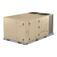
The LDT commercial combination heat pump and gas
-
 -
frigerant systems utilize two compressors, two reversing

common to a heat pump. Units are available in 130,000,

inputs. Gas heat sections are designed with stainless
steel tube heat exchangers.
-
rect drive blowers. These units will provide supply air at
lower speeds when cooling demand is low and increase
to higher speeds when cooling demand is high. Refer to
Supply Air Start-Up sections.
󰀨
energy management thermostat control systems with min-

Information contained in this manual is intended for use

subject to change. Procedures outlined in this manual are
presented as a recommendation only and do not super-
sede or replace local or state codes.
If the unit must be lifted for service, rig unit by attaching
four cables to the holes located in the unit base rail (two

for the proper rigging technique.
LDT
6.5 / 7.5 / 8.5 / 10 / 12.5
100086
LDT DUAL FUEL SERIES
Question and Answer IconNeed help?

Do you have a question about the Lennox LDT DUAL FUEL Series and is the answer not in the manual?

Lennox LDT DUAL FUEL Series Specifications

General IconGeneral
BrandLennox
ModelLDT DUAL FUEL Series
CategoryAir Handlers
LanguageEnglish

Summary

Safety Warnings and Unit Overview

General Safety Precautions

Essential safety warnings for operation, maintenance, and electrical hazards.

LDT Unit Description

Overview of the LDT commercial combination heat pump and gas unit.

LDT Specifications

Cooling and Heating Performance Data

Detailed performance data for cooling and heating capacities across models.

Component Specifications Overview

Specs for coils, blowers, and electrical characteristics of LDT units.

Gas Heat Specifications

Gas Heat Performance Details

Input/output capacities, temperature rise, and thermal efficiency.

High Altitude Derate Information

Derating guidelines for gas manifold pressure at higher altitudes.

Blower Data Tables

Blower Performance Data

Static pressure resistance data for various air volumes and unit configurations.

Electrical Data

6.5 Ton Electrical Ratings

Electrical ratings for compressors, fans, and components for 6.5 Ton models.

7.5 Ton Electrical Ratings

Electrical ratings for compressors, fans, and components for 7.5 Ton models.

Unit Components and Diagrams

LDT Unit Parts Arrangement

Illustration showing the physical layout of major LDT unit components.

Control Box Component Identification

Visual identification of components within the unit's main control box.

Unit Component Details

Control Box Component Functions

Descriptions of transformers, relays, and switches in the control box.

Electrostatic Discharge (ESD) Precautions

Safety guidelines for handling electronic components to prevent ESD damage.

Plumbing Components

Refrigerant Circuit Diagrams

Visual representation of refrigerant flow paths for different LDT unit models.

Cooling System Components

Compressors and Protection Features

Details on compressors, freezestats, and pressure switches for system protection.

Important Operational Notes

Key operational notes on compressor protectors and their behavior.

Refrigeration System Components

Reversing Valve and Defrost Controls

Explanation of reversing valve function and defrost switch operation.

Other Refrigeration System Parts

Information on filter driers, fan motors, heaters, and sensors.

Blower System Operation

Blower Compartment and Access

Procedures for accessing and servicing the blower compartment.

Blower Calibration and Settings

Steps for calibrating the blower and adjusting cooling speeds via the controller.

Blower Parameter Settings

Direct Drive Blower Settings Table

A table detailing adjustable parameters for blower speed and operation modes.

Gas Heat Components

Heat Exchanger and Burner Assembly

Details on the heat exchanger, inserts, and burner box assembly.

Burner Operation and Maintenance

Information on burner type, factory settings, and basic maintenance.

Gas Heat System Controls

Orifices, Limits, and Switches

Orifice sizing, primary limits, and combustion air switches.

Combustion Air Inducer and Controls

Operation of the combustion air inducer and its related safety controls.

Gas Heat Ignition System

Gas Valves and Spark Electrode

Description of gas valve operation and spark electrode assembly.

Flame Sensor Functionality

How the flame sensor detects ignition and ensures safety.

Burner Control System

Burner Control A3 and LED Diagnostics

Details on the burner control board and its diagnostic LED codes.

Ignition Sequence Timing

Normal and retry ignition sequences with specific timing information.

Unit Startup and Checks

Preliminary and Seasonal Checks

Essential pre-operation checks and seasonal maintenance procedures.

Heat Pump Startup Procedure

Steps for initiating heat pump operation based on ambient temperature.

Safety and Operation Procedures

Critical Safety Warnings

Warnings regarding explosion, electric shock, and smoke potential during operation.

Gas Valve Operation and Startup

Procedures for gas valve operation and safely placing the unit into service.

Unit Startup and Safety Procedures

Cooling Startup and Voltage Phasing

Procedures for cooling startup and ensuring correct compressor voltage phasing.

Emergency Shutdown Procedures

Steps for safely shutting down the unit in emergency situations.

System Service Checks

Refrigerant Charging Procedures

Methods for charging and checking refrigerant levels using pressure readings.

Subcooling Method for Charge Confirmation

Using subcooling measurements to verify correct refrigerant charge.

Gas Piping and Pressure Testing

Gas Piping Installation and Leak Testing

Guidelines for gas piping installation and leak detection methods.

Gas Supply Pressure Testing

Procedures for testing natural and propane gas supply pressure at the unit.

Gas System Adjustments and Checks

Manifold Pressure Adjustment

Adjusting manifold pressure for proper gas flow and stable flame.

Flame Sensing and Cooling Checks

Flame sensing procedures and cooling system service checks.

Maintenance Procedures

Filter and Coil Cleaning

Instructions for cleaning air filters, indoor, and outdoor coils.

Blower Wheel and Filter Drier Maintenance

Maintenance for the blower wheel and filter drier replacement.

Optional Accessories

Mounting Frames and Transitions

Details on roof mounting frames and duct transitions for installation.

Diffusers and Outdoor Air Dampers

Information on air diffusers and optional outdoor air damper accessories.

Economizer Operation

Economizer Modes and Setpoints

Configuration of different economizer operating modes and setpoints.

Economizer and Exhaust Systems

Barometric Relief Dampers

Function and installation of barometric relief dampers for air discharge.

Power Exhaust Fan System

Operation and setpoint adjustment for the power exhaust fan.

Control Systems and Kits

Enthalpy Controller and Thermostat Switches

Operation of enthalpy controller and various thermostat switches.

Optional Kits for Operation

Details on LP/Propane kits and cold weather kits for unit operation.

Wiring Diagrams and Sequences

Gas Heat Wiring Diagram (Y Voltage)

Wiring schematic for gas heat operation with Y voltage supply.

Gas Heat Wiring Diagrams

Gas Heat Wiring Diagram (J Voltage)

Wiring schematic for gas heat operation with J voltage supply.

Gas Heat Sequence of Operation

Heating Stage Operation Details

Step-by-step operation for first and second stage heating modes.

Thermostat Wiring Diagram

Thermostat Connections to Unit Controller

Wiring diagram detailing thermostat connections to the unit controller.

Economizer Wiring Diagram

Economizer Control Wiring Schematic

Schematic for connecting economizer sensors and control wiring.

Y Voltage Wiring Diagram

Y Voltage Control Circuitry

Wiring diagram illustrating Y voltage supply and control circuits.

G Voltage Wiring Diagram

G Voltage Control Circuitry

Wiring diagram illustrating G voltage supply and control circuits.

J Voltage Wiring Diagram

J Voltage Control Circuitry

Wiring diagram illustrating J voltage supply and control circuits.

Unit Sequence of Operation

Cooling Sequence of Operation

Step-by-step operation for first and second stage cooling modes.

Heating and Defrost Sequence

Heating Operation by Ambient Temperature

Heating operation logic based on ambient temperature and demand.

Defrost Mode Initiation Criteria

Conditions and timing for initiating the unit's defrost cycle.

Blower Operation and Troubleshooting

Direct Drive Blower Sequence

Sequence of operation for the direct drive blower motor.

Blower Fault Troubleshooting

Procedures for diagnosing and resolving common blower faults.

Related product manuals