Page 32
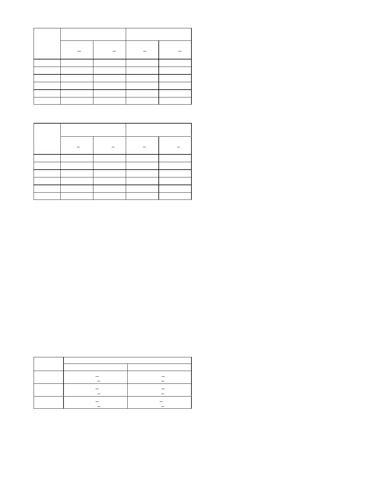
TABLE 9
180 Compressor 1 Frequency 56Hz - 581168-01
Outdoor
Coil En
tering
Air
Temp
Circuit 1 Circuit 2
Dis. +10
psig
Suc. +5
psig
Dis. +10
psig
Suc. +5
psig
65°F 243 133 248 132
75°F 280 137 286 135
85°F 321 141 328 138
95°F 366 144 374 140
105°F 415 146 424 143
115°F 469 149 477 146
TABLE 10
240 Compressor 1 Frequency 68Hz - 581169-01
Outdoor
Coil En
tering
Air
Temp
Circuit 1 Circuit 2
Dis +10
psig
Suc +5
psig
Dis. +10
psig
Suc +5
psig
65 °F 260 135 264 135
75 °F 297 136 304 136
85 °F 338 138 346 138
95 °F 384 140 394 140
105 °F 434 142 443 142
115 °F 485 144 494 144
B-Charge Verification - Approach Method - AHRI
Testing (Fin/Tube Coil)
1- Using the same thermometer, compare liquid
temperature to outdoor ambient temperature.
Approach Temperature = Liquid temperature (at
outdoor coil outlet) minus ambient temperature.
2- Approach temperature should match values in table
11. An approach temperature greater than value
shown indicates an undercharge. An approach
temperature less than value shown indicates an
overcharge.
3- The approach method is not valid for grossly over or
undercharged systems.
Use tables 9 through 10 as a
guide for typical operating pressures.
TABLE 11
APPROACH TEMPERATURES - FIN/TUBE COIL
Unit
Liquid Temp. Minus Ambient Temp.
1st Stage 2nd Stage
156
5°F + 1
(2.8°C +
0.5)
4.0°F + 1
(2.2°C +
0.5)
180
2°F + 1
(1.1°C +
0.5)
5.0°F + 1
(2.8°C +
0.5)
240
6°F + 1
(3.3°C +
0.5)
6°F + 1
(3.3°C +
0.5)
IV- START-UP OPERATION
A-Preliminary and Seasonal Checks
1- Make sure the unit is installed in accordance with the
installation instructions and applicable codes.
2- Inspect all electrical wiring, both field and factory
installed for loose connections. Tighten as required.
Refer to unit diagram located on inside of unit control
box cover.
3- Check to ensure that refrigerant lines are in good
condition and do not rub against the cabinet or other
refrigerant lines.
4- Check voltage. Voltage must be within the range listed
on the nameplate. If not, consult power company and
have the voltage corrected before starting the unit.
5- Recheck voltage and amp draw with unit running. If
voltage is not within range listed on unit nameplate,
stop unit and consult power company. Refer to unit
nameplate for maximum rated load amps.
6- Inspect and adjust blower belt (see section on Blower
Compartment - Blower Belt Adjustment).
B-Cooling Start-up
NOTE-Crankcase heaters must be energized 24 hours
before attempting to start compressor. Set thermostat so
that there is no demand to prevent compressor from
cycling. Apply power to unit.
1-- Initiate first and second stage cooling demands
according to instructions provided with thermostat.
2- First-stage thermostat demand will energize indoor
blower in Low Cooling CFM. Second-stage thermostat
demand will energize indoor blower in High Cooling
CFM. Both demands energize compressor 1. The
remaining compressors will be energized as needed to
meet cooling demand.
3- 156, 180 and 240 units contain two refrigerant circuits
or systems.
4- Each refrigerant circuit is separately charged with
R410A refrigerant. See unit rating plate for correct
amount of charge.
5- Refer to the Refrigerant Check and Charge section to
check refrigerant charge.
C-Heating Startup
Heat Pump Mode
1- Set thermostat or temperature control device to initiate
a first-stage heating demand..
2- Outdoor Temperature ABOVE Balance Point
Set-point (35°F default):
A first-stage heating demand (W1) will energize
compressor heat pump heating, the outdoor fans, and
the blower.
A second-stage heating demand (W2) will de-energize
compressor heat pump heating and High Gas Heat will
be energized..
3- Outdoor Temperature BELOW Balance Point
Set-point (35°F default):
A first-stage heating demand (W1) will energize low
gas heat and the blower motor.
A second-stage heating demand (W2) will energize
high gas heat.
 Loading...
