Page 8
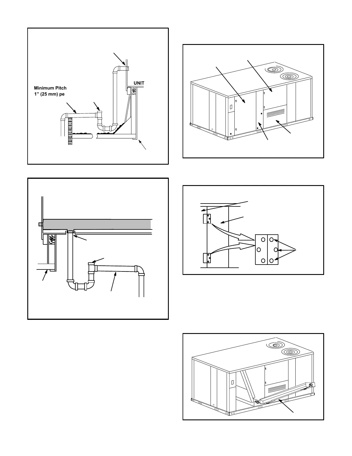
FIGURE 3
UNIT
Minimum Pitch
1” (25 mm) per
10' (3 m) of line
MOUNTING
FRAME
OPEN VENT
CONDENSATE SIDE DRAIN CONNECTION
NOTE - Allow clearance to
open doors when installing
condensate piping.
CAULK AROUND CONDENSATE COUPLING
FIGURE 4
UNIT
Minimum Pitch
1” (25 mm) per 10'
(3 m) of line
MOUNTING
FRAME
CONDENSATE BOTTOM DRAIN CONNECTION
OPEN VENT
CAULK AROUND
CONDENSATE COUPLING
DRAIN PAN
Units are shipped with the drain coupling facing the front
of the unit. Condensate can be drained from the back or
bottom of the unit with the following modifications. The
unit can be installed in either downflow or horizontal air
discharge regardless of condensate drain location.
Rear Drain Connection
1- Open blower and heat access doors. See figure 5.
FIGURE 5
CONDENSATE
DRAIN MULLION
BLOWER
ACCESS DOOR
HEAT
ACCESS DOOR
FILTER
ACCESS DOOR
2- Remove six screws from filter access door. Refer to
figure 6.
REMOVE
THREE
SCREWS
(PER HINGE)
FIGURE 6
CONDENSATE
DRAIN MULLION
UNITS WITH HINGED PANELS
FILTER DOOR
3- Open filter access door hinges and carefully remove
door.
4- Remove eight screws holding condensate drain
mullion and remove mullion.
5- Lift front edge of the drain pan (to clear bottom drain
plug) and slide drain pan out of unit. See figure 7.
FIGURE 7
DRAIN PAN
 Loading...