11- Thecombustionair inducerwillstart,Theburners
willlightwithin40seconds,
12- Ifthefurnacedoesnotlightthefirsttime(gaslinenot
fullypurged),itwillattemptuptotwomoreignitions
beforelockingout,
13- Iflockoutoccurs,repeatsteps1through10,
14- Ifthefurnacewillnotoperate,followtheinstructions
"TurningOffGastoFurnace"andcallyourservice
technicianorgassupplier.
TurningOffGastoFurnace
1- Ifusinganelectromechanicalthermostat,settothe
lowestsetting.
2- Beforeperforminganyservice,turnoffallelectrical
powertothefurnace.
3- Openorremovetheheatsectionaccesspanel.
4- 36C, VR8205, & VR8305-
Turn the knob on the gas valve clockwise _ to
"OFF". Depress 36C knob slightly. Do not force.
36E -
Turn the knob 180° either way to "OFF".
5- Close or replace the heat section access panel.
A,WARNING
To maintain efficiency and longevity, your equipment
must be serviced yearly by a qualified service technician.
Failure to provide proof of service can void warranty.
A,CAUTION
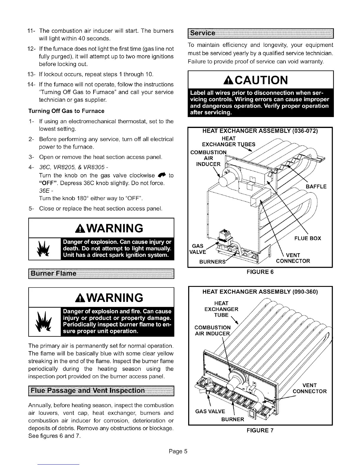
HEAT EXCHANGER ASSEMBLY (036-072)
HEAT
EXCHANGER T
COMBUSTION
AIR
INDUCER
\
BAFFLE
FLUE BOX
GAS
VALVE
VENT
CONNECTOR
FIGURE 6
HEAT EXCHANGER ASSEMBLY (090-360)
&WARNING
The primary air is permanently set for normal operation.
The flame will be basically blue with some clear yellow
streaking in the end d the flame, Inspect the burner flame
periodically during the heating season using the
inspection port provided on the burner access panel.
Annually, before heating season, inspect the combustion
air louvers, vent cap, heat exchanger, burners and
combustion air inducer for corrosion, deterioration or
deposits of debris. Remove any obstructions or blockage.
See figures 6 and 7.
HEAT
EXCHANGER
TUBE
COMBUSTION
AIR
VENT
GAS VALVE
BURNER
FIGURE 7
Page 5
 Loading...