Page 2
TABLE 3
Mode
Field−Provided
Sensors
Dampers will modulate to 55°F
discharge air (RT6) when:
TMP None Needed
OA temp. (RT17) is less than RA
temp. (RT16) or when the Energy
Management System sends an
economizer enable message.**
ODE C7400
OA enthalpy* (A7) is less than
enthalpy setpoint.
DIF (Two) C7400
OA enthalpy (A7) is less than
RA enthalpy (A62).
GLO
Energy Manage-
ment System With
Global Output
Global input is energized.
*Temperature + humidity= enthalpy.
**Energy management systems may require additional
field−provided sensors; refer to manufacturer’s instructions.
Install Economizer − Downflow
1− Open unit end panel and filter access panel. See
figure 1. When gravity or power exhaust are
field−installed, remove and discard the lower panel.
2− Remove and retain sensors from mounting bracket.
See figure 2. Remove mounting bracket and discard.
3− Install damper assembly through end of unit. Fit
opening in bottom of damper assembly over the
return air opening. See figure 4.
4− Install retained sensors in the side of the economizer.
See figure 4.
5− Disconnect jumper plug P3 from unit jack J3.
Connect economizer plug P4 to unit jack J3 as
shown in figure 3.
Lower panel provided only when economizer is
factory−installed without gravity or power exhaust.
Remove and discard when field−installing
GED and/or PEF.
FIGURE 1
UNIT
FILTER ACCESS
PANEL
UNIT END
PANEL
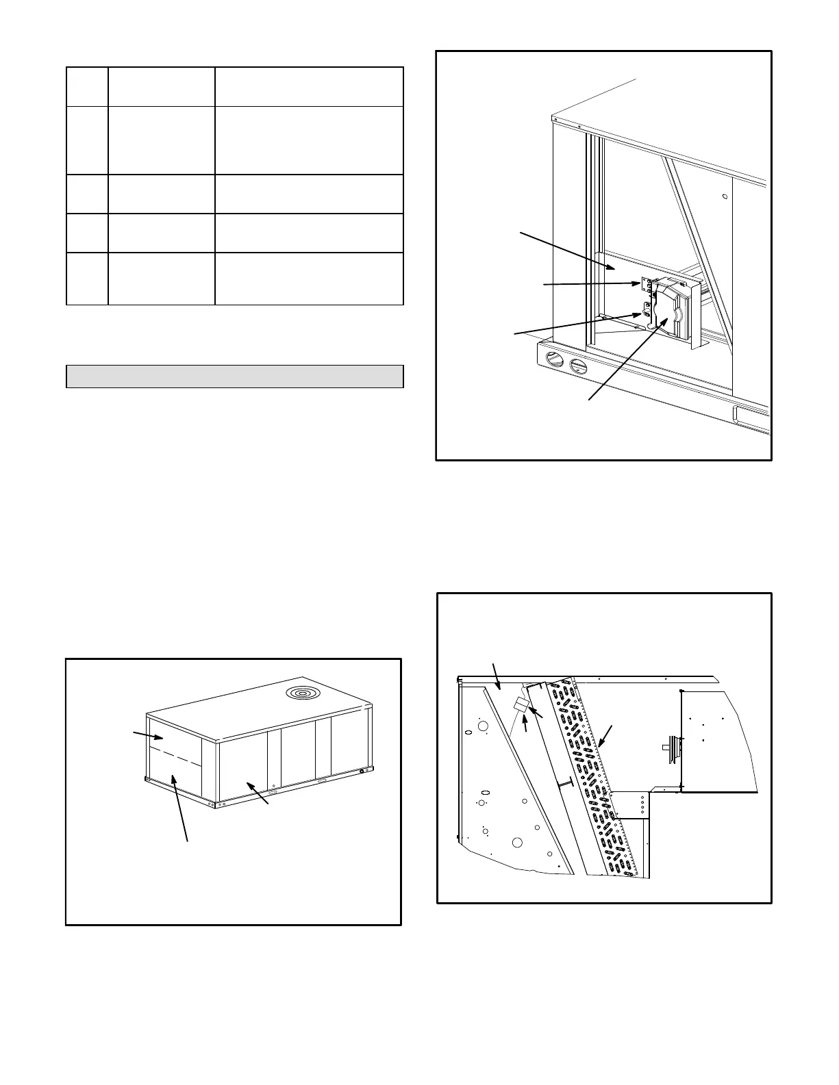
FIGURE 2
REMOVE SENSORS AND BRACKET
SENSOR
BRACKET
A2 SENSOR
(UNITS WITH DDC
CONTROL)
RT16
SENSOR
SMOKE DETECTOR
(WHEN EQUIPPED)
FIGURE 3
CONNECT ECONOMIZER PLUG P4 TO
UNIT JACK J3
FILTER
SECTION
EVAPORATOR
COIL
J3
P4
 Loading...
