Page 44
LGH/LCH036, 048, 060, 072
WARNING
Units are shipped from the factory with temporary
filters. Replace filters before building is occupied.
Damage to unit could result if filters are not re
placed with approved filters. Refer to appropriate
codes.
Approved filters should be checked monthly and
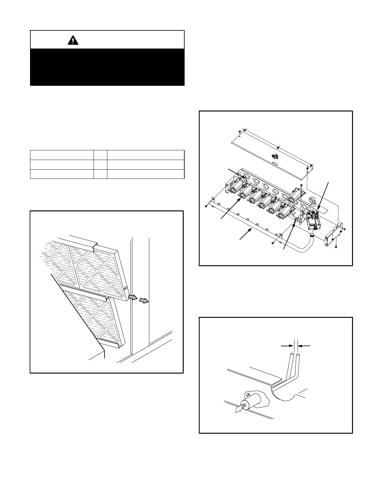
replaced when necessary. Take note of air flow direction
marking on filter frame when reinstalling filters. See
figure 31.
TABLE 32
UNIT FILTERS
Unit Qty Filter Size - inches (mm)
036, 048 4 16 X 20 X 2 (406 X 508 X 51)
060, 072 4 20 X 20 X 2 (508 X 508 X 51)
NOTE-Filters must be U.L.C. certified or equivalent for
use in Canada.
FIGURE 31
REMOVE FILTERS
PULL TO
REMOVE
FILTERS
B-Lubrication
All motors are lubricated at the factory. No further
lubrication is required.
C-Burners (Gas Units)
Periodically examine burner flames for proper
appearance during the heating season. Before each
heating season examine the burners for any deposits or
blockage which may have occurred.
Clean burners as follows:
1- Turn off both electrical power and gas supply to unit.
2- Remove burner compartment access panel.
3- Remove top burner box panel.
4- Remove two screws securing burners to burner
support and lift the burners from the orifices. See
figure 32. Clean as necessary.
FIGURE 32
BURNER BOX ASSEMBLY
GAS VALVE
GAS
MANIFOLD
FLAME
SENSOR
BURNERS
IGNITOR
5- Locate the ignitor under the right burner. Check
ignitor spark gap with appropriately sized twist drills
or feeler gauges. See figure 33.
FIGURE 33
IGNITOR
SPARK GAP
SHOULD BE 1/8”
(3mm)
6- Replace burners and screws securing burner. See
figure 34.
 Loading...
