Page 17
PLUMBING, COMPRESSOR AND REFRIGERANT CIRCUITS DETAIL
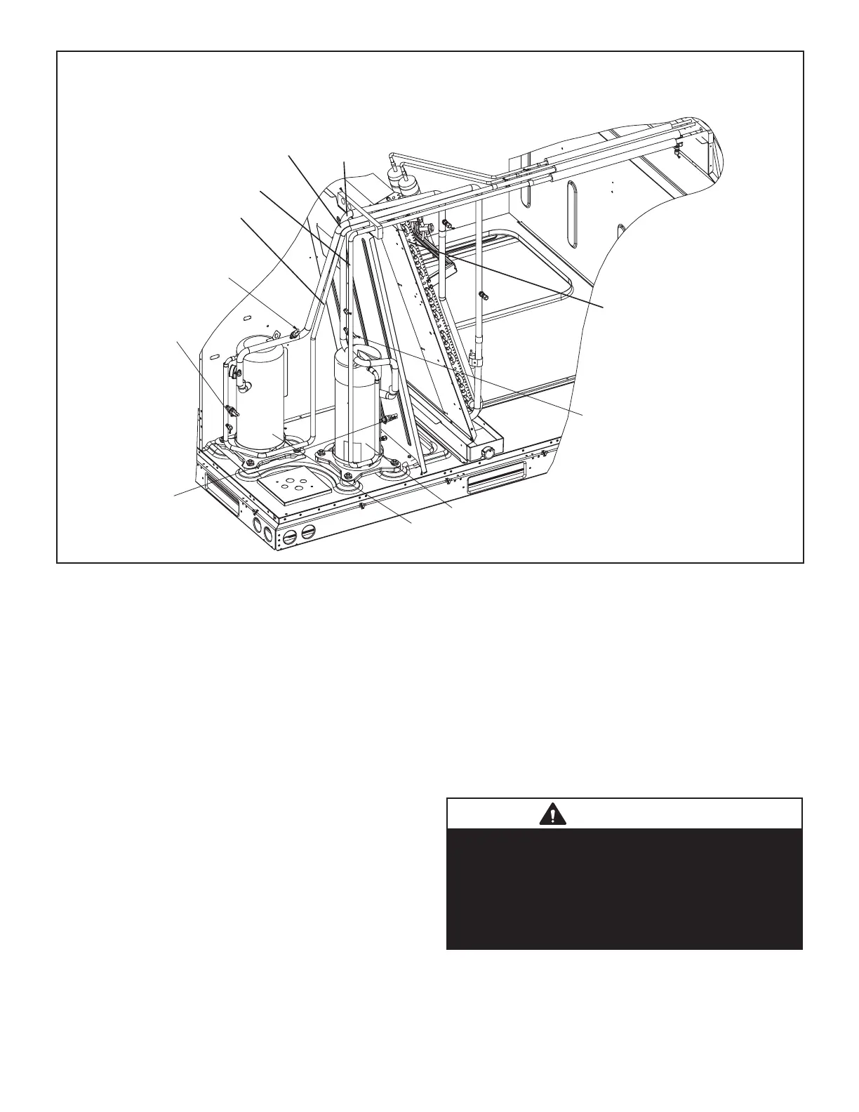
FIGURE 6
Low Pressure Switch
S87
Low Pressure Switch
S88
High Pressure
Switch
S4
High Pressure
Switch
S7
Evaporator Coil
Compressor
B1
Compressor
B2
Discharge Line
Stage 1
Discharge Line
Stage 2
Suction Line
Stage 1
Suction Line
Stage 2
B-Cooling Components
High efficiency units use independent cooling circuits con
sisting of separate compressors, condenser coils and
evaporator coils. See figure 6. Units are equipped with
ECM direct drive blowers which draw air across the evapo
rator during unit operation..
On all units the evaporators are slab type and are row split..
Each evaporator uses a thermostatic expansion valve as
the primary expansion device..
In all units, each compressor is protected by a crankcase
heater, high pressure switch and low pressure switch. Ad
ditional protection is provided by by thermistors for low am
bient control and freezing prevention.
Cooling may be supplemented by a factory‐ or field‐in
stalled economizer.
1-Compressors B1, B2
Units are equipped with two scroll compressors and two in
dependent cooling circuits. B1 is 2-stage compressor, with
L34 to switching between part load and full load, B2 is sin
gle stage compressor. Compressor capacity may vary from
stage to stage. In all cases, the capacity of each compres
sor is added to reach the total capacity of the unit. See
“SPECIFICATIONS” and “ELECTRICAL DATA” (table of
contents) or compressor nameplate for compressor speci
fications.
WARNING
Electrical shock hazard. Compressor must be
grounded. Do not operate without protective cover
over terminals. Disconnect power before removing
protective cover. Discharge capacitors before ser
vicing unit. Failure to follow these precautions could
cause electrical shock resulting in injury or death.
 Loading...


