Page 40
VII-ACCESSORIES
The accessories section describes the application of most
of the optional accessories which can be factory or field in
stalled to the LGT units.
A-Mounting Frames
When installing units on a combustible surface for down
flow discharge applications, a C1CURB roof mounting
frame is used. The roof mounting frames are recommend
ed in all other applications but not required. If the LGT units
are not mounted on a flat (roof) surface, they MUST be sup
ported under all edges and under the middle of the unit to
prevent sagging. The units MUST be mounted level within
1/16” per linear foot or 5mm per meter in any direction.
The assembled C1CURB mounting frame is shown in fig
ure 27. Refer to the roof mounting frame installation instruc
tions for details of proper assembly and mounting. The roof
mounting frame MUST be squared to the roof and level be
fore mounting. Plenum system MUST be installed before
the unit is set on the mounting frame. Typical roof curbing
and flashing is shown in figure 28. Refer to the roof mount
ing frame installation instructions for proper plenum con
struction and attachment.
FIGURE 27
ASSEMBLED ROOF MOUNTING FRAME
SUPPLY AIR
OPENING
RETURN AIR
OPENING
B-LP / Propane Kit
Natural to LP /propane kit includes a spring kit and three
stickers. In addition, the LP kit contains either six, nine, or
eleven burner orifices. For more detail refer to the natural to
LP gas changeover kit installation instructions.
C-Dirty Filter Switch S27
The dirty filter switch senses static pressure increase indi
cating a dirty filter condition. The switch is N.O. and closes
at 1” W.C. (248.6 Pa) The switch is mounted on the top filter
channel corner. Wiring for the dirty filter switch is shown on
the temperature control section (C2) wiring diagram in back
of this manual.
FIGURE 28
ROOF
MOUNTING FRAME
(Extends around entire
perimeter of unit)
FIBERGLASS
INSULATION
(Furnished)
COUNTER FLASHING
(Field Supplied)
UNIT BASE
BOTTOM
RIGID INSULATION
(Field Supplied)
ROOFING
MATERIAL
CANT STRIP
(Field Supplied)
NAILER STRIP
(Furnished)
UNIT BASE
RAIL
TYPICAL FLASHING DETAIL
D-Transitions
Optional supply/return transitions LASRT08/10 is available
for use with the LGT 7.5 ton units and LASRT10/12 is avail
able for the 8.5 and 10 ton units, utilizing optional C1CURB
roof mounting frames. LGT 12.5 ton units will use LASRT15
with C1CURB roof mounting frame. Transition must be in
stalled in the C1CURB mounting frame before mounting
the unit to the frame. Refer to the manufacturer's instruc
tions included with the transition for detailed installation
procedures.
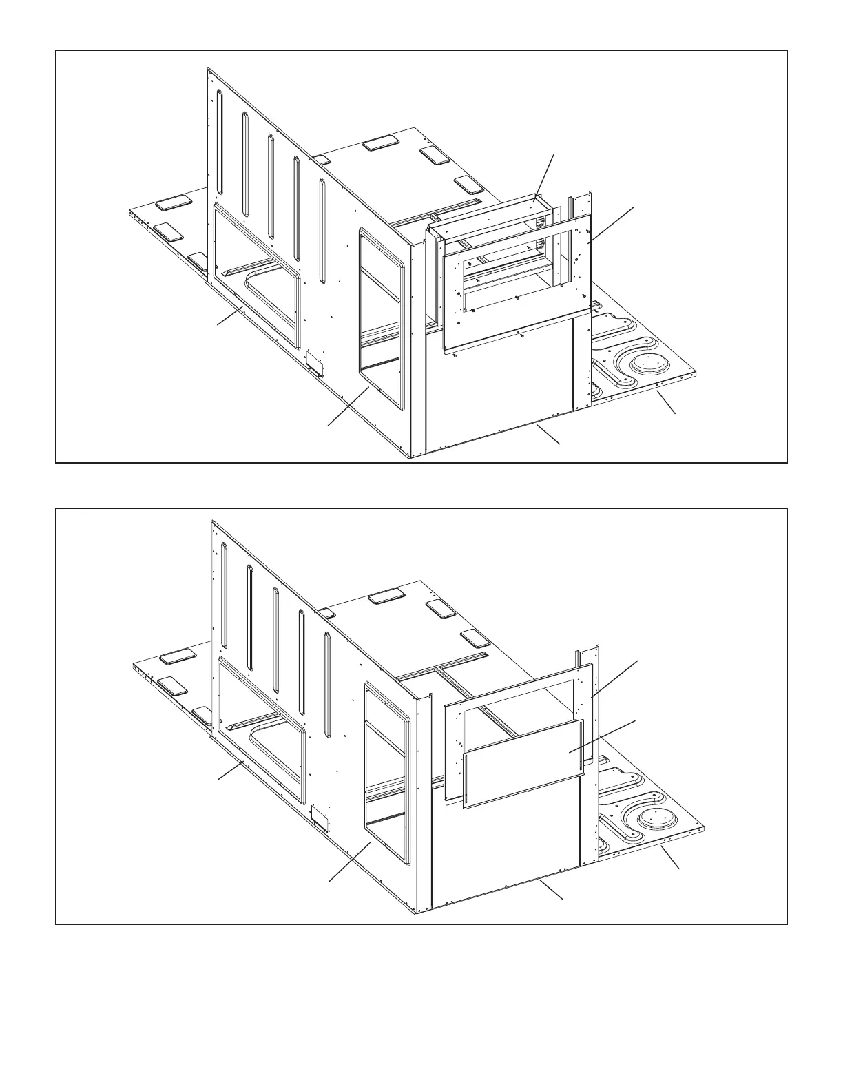
E-LAOAD(M) Outdoor Air Dampers (all
units)
LAOAD(M) consists of a set of dampers which may be man
ually or motor (M) operated to allow up to 25 percent out
side air into the system at all times (see figure 29 or 30). Ei
ther air damper can be installed in LGT units. Washable
filter supplied with the outdoor air dampers can be cleaned
with water and a mild detergent. It should be sprayed with
Filter Handicoater when dry prior to re-installation.
F-Supply and Return Diffusers (all units)
Optional flush mount diffuser/return FD11 and extended
mount diffuser/return RTD11 are available for use with all
LGT units. Refer to manufacturer's instructions included
with transition for detailed installation procedures.
G-Blower Proving Switch S52
The blower proving switch monitors blower operation and
locks out the unit in case of blower failure. The switch is
N.O. and closes at .14” W.C. (34.9 Pa) The switch is mount
ed on the upper left hand corner of the blower deck. Wiring
for the blower proving switch is shown on the temperature
control section (C2) wiring diagram in back of this manual.
 Loading...


