20
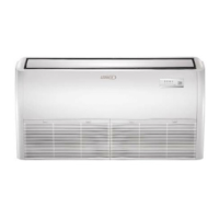
From Power
Supply
Indoor Unit
CommunicationTerminal Block
L1 L2
Power Terminal Block
208/230V Outdoor Unit
L1 L2
L1 L2
Power Terminal Block
208/230V Outdoor Unit
Power Terminal Block
208/230V Indoor Unit
S1 S2
Communication Terminal Block
Outdoor Unit
E Y X
Y
Q
S1
E P
S2
Outdoor Unit
Indoor Unit
Figure 30. Single Zone Wiring 36K & 48K Only
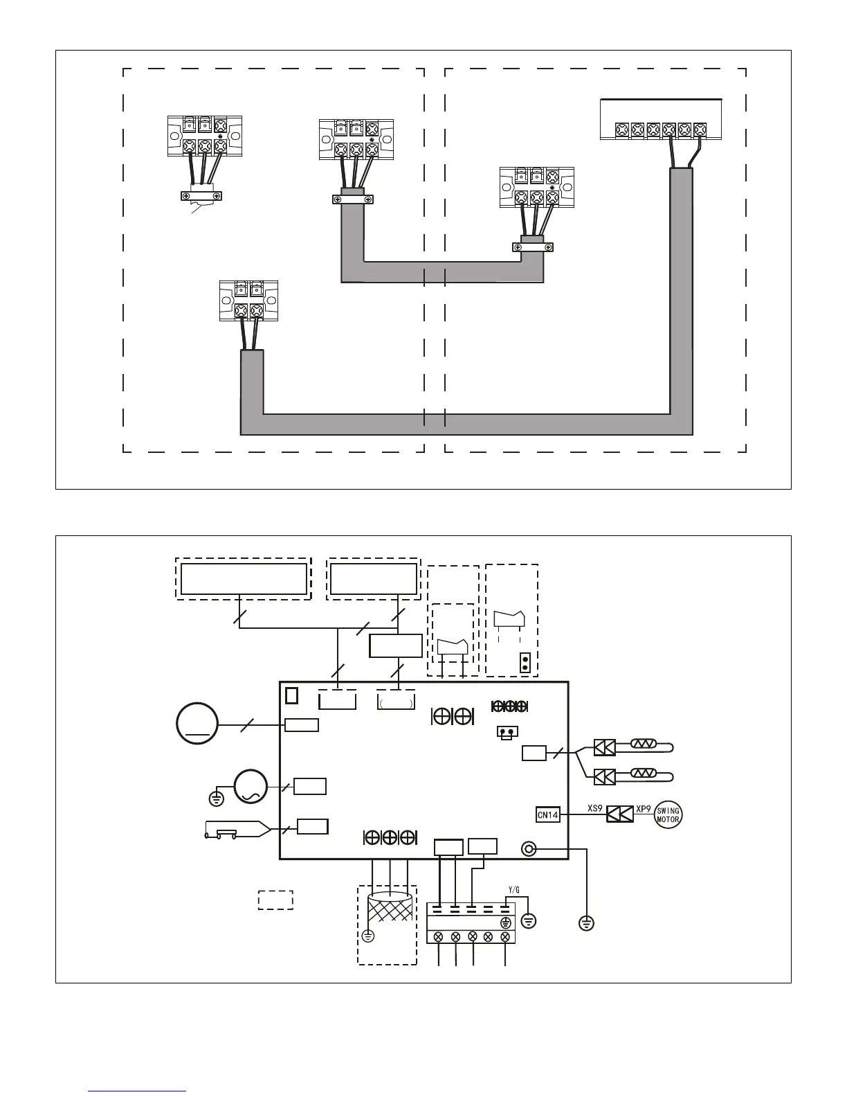
1 2 3
CN13
D IS P LA Y
B O A R D
10
T2
T1
CN6
4
ROO M T EMP .SEN SOR
BL AC K
WH ITE
CN 10 A
M
PU MP
2
INDOOR UNIT
MAINBOARD
TO WIRED
CONTROLLER
5
CN23
ON - OFF
Remote
Control
CN3 3
ALA RM
Alarm
Output
CN1 5
M
Motor
5
R E D (B R O W N )
CN1
B L U E (B L A C K )
CN5
W AT E R L EVEL S W IT C H
E Y X
To LVM
Comm.Bus
P1
CN3
JR6
JR6
2
Y/G
C N 11 0
Y E L L O W
P5
CN 10
INDOOR COIL TEMP.SENSOR
Note1: Remove the JR6 jumper
for remote on /off contr ol
CN 40
TO PROGRAMMABLE
WIRED CONTROLLER
2
2
NOTE:
COMPONENT IN DASH
LINE IS OPTIONAL
OR FIELD WIRING.
Note: The programmable
wired controller and regular
wired controller use the same
wiring connector.
4
Figure 31. M22A009S4-*P, M22A012S4-*P, M22A018S4-*P, M33A024S4-*P Unit Wiring Diagram
 Loading...