21
CN13
DISPLAY
BOARD
TO WIR E
CON TRO LLE R
10
T2
T1
CN6
4
BLACK
WHITE
CN10(CN10A)
M
PUMP
2
INDOOR UNIT
MAIN BOARD
C N 2 3
O N - O F F
Remote
Control
C N 3 3
A L A R M
Alarm
Output
CN 15
M
FAN
5
R E D (B R O W N )
CN1
B L U E (B L A C K )
L1
L2
Y/G
CN5
W ATE R LE V E L S W IT C H
CN2
Q E P
To LVM
Comm.Bus
CN7
T2B
INDOOR COIL OUTLET TEMP.SENSOR
POWER
P1
Y/G
CN3
JR6
JR6
To O UTDOO R
Comm .Bus
S2
S1
P4
E Y X
Ferrite b e a d
5
ROO M T EMP .SEN SOR
INDO OR C OIL T EMP .SENS OR
Note1:remove the JR6 jumper for
remote on/off control
TO
PROGRAMMABLE
WIRED
CONTROLLER
2
CN40
4
Note: The
programmable
wired controller
and regular
wired controller
use the same
wiring con nector
2
• • • • •
COMPONENT IN DASH
LINE IS OPTIONAL
OR FIELD WIRING.
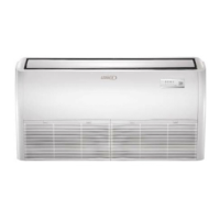
Figure 32. M33A036S4-*P, M33A048S4-*P and M33B048S4-*P Unit Wiring Diagram
BLUE
CN2
BROWN
CN16
CN1
CN26
DC-FAN
CN29
REACTOR
CN9-1
CN32-1
OUTDOOR
COIL TEMP. SENS
OR
CN7
COMPRESSOR
DISCHARGE TEMP. SENSOR
CN27
YELLOW
4-WAY
VALVE
WHITE
COMPRESSOR
BLUE
RED
BLACK
CN28
CN30
WHITE
3
2
L2
RED
BLUE
Y/G
1
Y/G
Y/G
CN3
6
CN31
CN21
CN22
3
PAN
HEATER
CN33
CRANKCASE
HEATER
OUTDOOR TEMP. SENSOR
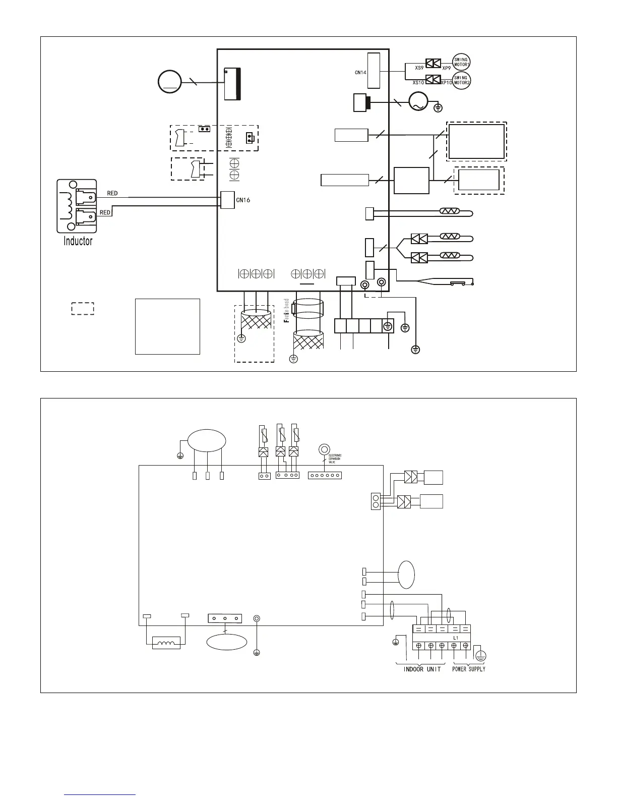
Figure 33. 208/230V MPA009S4S-*P and MPA012S4S-*P Outdoor Unit Wiring Diagram
 Loading...