Do you have a question about the Lennox MCB024S4S-1P and is the answer not in the manual?
Specifies required clearance dimensions around the outdoor unit for proper operation.
Lists error codes and LED indicators for troubleshooting indoor and outdoor units.
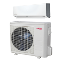
This document is an installation and service information manual for Lennox MCB and MWCB Series Single-Zone Mini-Split Systems (115V and 208/230V). It provides detailed instructions for the installation, operation, and maintenance of these HVAC units.
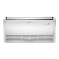
The Lennox MCB and MWCB Series units are single-zone mini-split air conditioning systems designed for residential or light commercial applications. They consist of an indoor wall-mounted unit matched with an outdoor air conditioner unit, using HFC-410A refrigerant. The system provides cooling and, depending on the model, may also offer heating capabilities. The manual emphasizes proper installation to ensure optimal performance, safety, and longevity of the system.
Model Number Identification: The manual includes detailed model number identification charts for both outdoor single-zone air conditioner units and wall-mounted indoor units.
System Dimensions (Inches (mm)):
System Clearances:
Refrigerant Piping and Indoor Unit Connection Sizes:
Line Set Length and Elevation Parameters:
Electrical Specifications (Minimum Circuit Amps (MCA) and Max Fuse):
Refrigerant Oil: The compressor uses PVE oil (Polyvinylether), formulated for HFC-410A refrigerants. Mixing with mineral-based oil or POE oil is not recommended.
Wireless Remote Control: The system includes a wireless controller for operation. Indoor Unit Display: The indoor unit LED displays alert codes and operational status codes for troubleshooting. Manual Control Button: In situations where the ambient temperature is below 60°F (16°C) and the wireless remote control cannot activate the COOL function, a manual control button on the indoor unit can be used for testing.
Air Filter Maintenance:
Leak Test and Evacuation:
Torque Requirements:
Troubleshooting (Indoor Display Alert and Status Codes): The manual lists various error codes and their descriptions, displayed on the indoor unit LED or outdoor unit:
Construction Usage Guidelines: Lennox advises against using mini-split systems during construction due to potential damage from low return air temperatures, harmful vapors, and clogged filters. If used, specific conditions must be met: air filter installation and maintenance, filter replacement after construction, thorough cleaning of the indoor unit, and verification of all operating conditions.
| Refrigerant Type | R-410A |
|---|---|
| Voltage | 208/230V |
| Sound Level (Outdoor Unit) | 74 dB |
| Cooling Capacity | 24, 000 BTU/h |
| Phase | Single |
| Dimensions (Outdoor Unit) | 31" x 31" |