Page 15
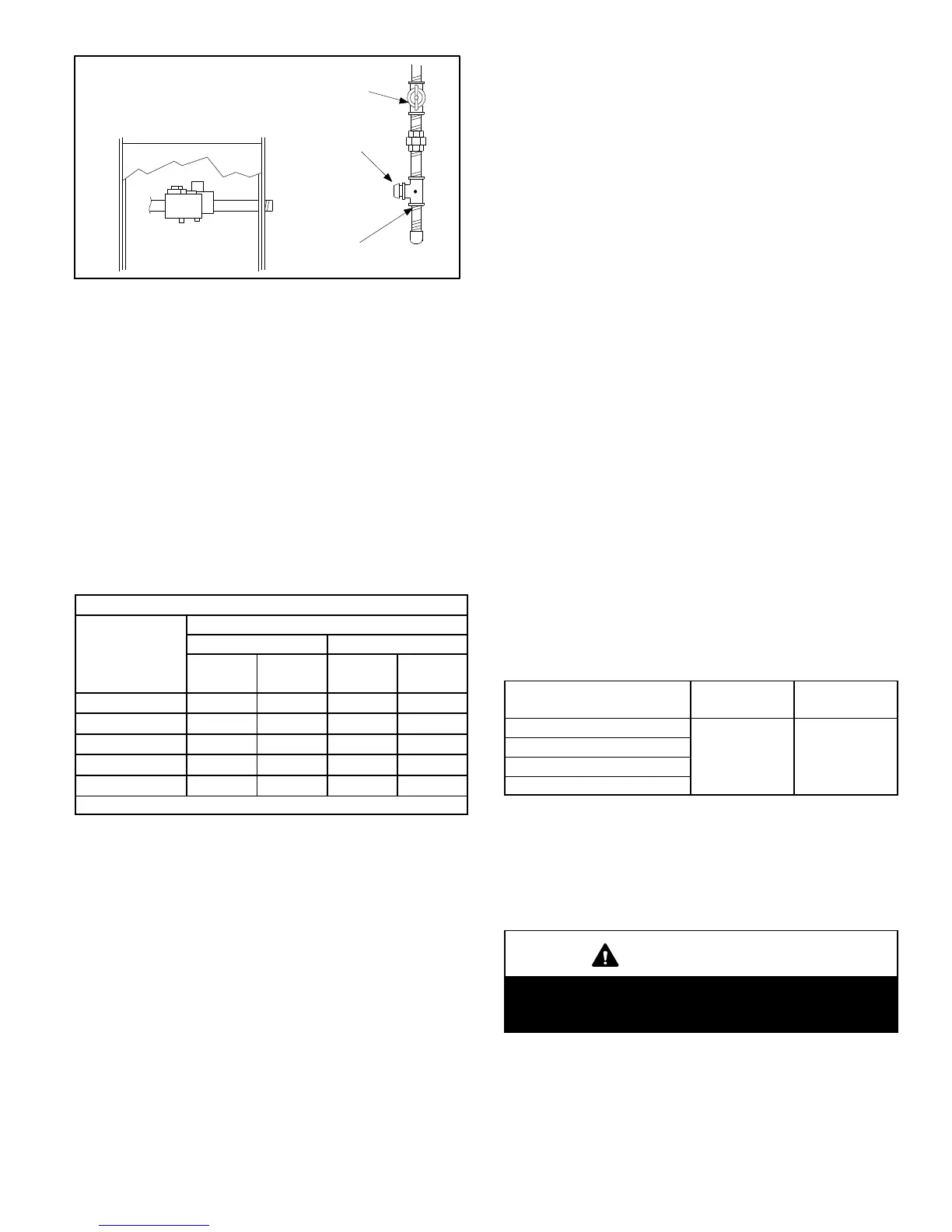
FIGURE 12
MANUAL MAIN SHUT-OFF VALVE
WILL NOT HOLD TEST PRESSURE
IN EXCESS OF 0.5 PSIG (14”W.C.)
GAS VALVE
CAP
GAS PIPING TEST PROCEDURE
FIELD PROVIDED
LINE PRESSURE TAP
When checking piping connections for gas leaks, use pre
ferred means. Kitchen detergents can cause harmful corro
sion on various metals used in gas piping. Use of a specialty
Gas Leak Detector is strongly recommended. It is available
through Lennox under part number 31B2001. See Corp.
8411-L10, for further details.
Do not use matches, candles, flame or any other source of
ignition to check for gas leaks.
D- Gas Pressure Adjustment
Gas Flow (Approximate)
TABLE 7
GAS METER CLOCKING CHART
ML180DF
Unit
Seconds for One Revolution
Natural LP
1 cu ft
Dial
2 cu ft
Dial
1 cu ft
Dial
2 cu ft
DIAL
-045 80 160 200 400
-070 55 110 136 272
-090 41 82 102 204
-110 33 66 82 164
-135 27 54 68 136
Natural-1000 btu/cu ft LP-2500 btu/cu ft
Furnace should operate at least 5 minutes before check
ing gas flow. Determine time in seconds for two revolu
tions of gas through the meter. (Two revolutions assures a
more accurate time.) Divide by two and compare to time
in table 7. If manifold pressure matches table 9 and rate is
incorrect, check gas orifices for proper size and restric
tion. Remove temporary gas meter if installed.
NOTE - To obtain accurate reading, shut off all other gas
appliances connected to meter.
E- Supply and Manifold Pressure
Supply Pressure Measurement
1 - Remove the threaded plug from the inlet side of the
gas valve and install a field-provided barbed fitting.
Connect to a test gauge to measure supply pressure.
2 - Start unit and allow 5 minutes for unit to reach steady
state.
3 - After allowing unit to stabilize for 5 minutes, record
supply pressure and compare to value given in table 9.
Manifold Pressure Measurement
1 - Remove the threaded plug from the outlet side of the
gas valve and install a field-provided barbed fitting.
Connect to a test gauge to measure manifold pres
sure.
2 - Start unit and allow 5 minutes for unit to reach steady
state.
3 - While waiting for the unit to stabilize, observe the
flame. Flame should be stable and should not lift from
burner. Natural gas should burn blue.
4 - After allowing unit to stabilize for 5 minutes, record
manifold pressure and compare to value given in table
9.
NOTE - Shut unit off and remove manometer as soon as an
accurate reading has been obtained. Take care to remove
barbed fitting and replace threaded plug.
F- Proper Combustion
Furnace should operate a minimum 15 minutes with cor
rect manifold pressure and gas flow rate before checking
combustion. Take combustion sample beyond the flue out
let and compare to the tables below. The maximum carbon
monoxide reading should not exceed 50 ppm.
TABLE 8
ML180DF Unit
CO
2
%
For
Nat
CO
2
%
For
L.P.
-045
6.0 - 7.5 6.9 - 8.5
-070
-090
-110
G- High Altitude
The manifold pressure may require adjustment and com
bustion air pressure switch may need replacing to ensure
proper combustion at higher altitudes. Refer to table 9 for
manifold pressure and table 10 for pressure switch change
and gas conversion kits.
IMPORTANT
For safety, shut unit off and remove manometer as
soon as an accurate reading has been obtained.
Take care to replace pressure tap plug.
 Loading...