Page 3
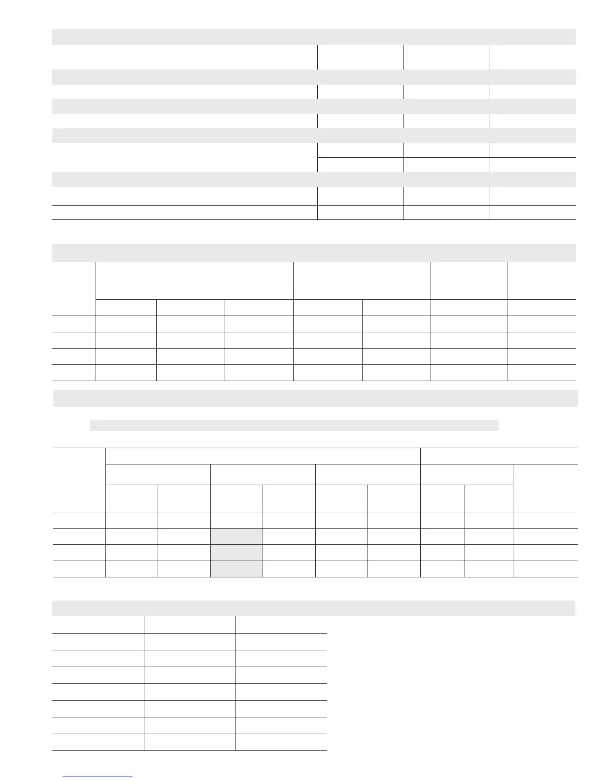
HIGH ALTITUDE DERATE
NOTE - Units may be installed at altitudes up to 4500 ft. above sea level without any modications.
At altitudes above 4500 ft. units must be derated to match information in the shaded areas shown below.
NOTE - This is the only permissible derate for these units.
Input
Gas Manifold Pressure (Outlet) in. w.g. Line Pressure - in. w.g.
0 - 4500 Feet 4501 - 7500 Feet 7501 - 10,000 ft. Minimum
Maximum
Natural
Gas
LPG/
Propane
Natural
Gas
LPG/
Propane
1
Natural
Gas
LPG/
Propane
Natural
Gas
LPG/
Propane
045 3.5 10 3.5 10 3.5 10 4.5 11 13
070 3.5 10 3.3 10 3.5 10 4.5 11 13
090 3.5 10 3.3 10 3.5 10 4.5 11 13
110 3.5 10 3.3 10 3.5 10 4.5 11 13
1
Natural Gas High Alitude Orice Kit required.
OPTIONAL ACCESSORIES - ORDER SEPARATELY
“A” Width
Models
“B” Width
Models
“C” Width
Models
CABINET ACCESSORIES
Downow Combustible Flooring Base 11M59 11M60 11M61
CONTROLS
Twinning Kit 15L38 15L38 15L38
FILTERS
1
Downow Filter Cabinet 51W06 51W07 51W08
No. and Size of lter - in. (1) 20 x 20 x 1 (2) 20 x 16 x 1 (2) 20 x 16 x 1
service kits
Night Service Kit 51W03 51W03 51W03
Universal Service Kit - Switches 89W19 89W19 89W19
1
Cleanable polyurethane, frame-type lter.
GAS HEAT ACCESSORIES
Input
High Altitude
Pressure Switch Kit
Natural Gas to
LPG/Propane Kit
LPG/Propane
to Natural Gas Kit
Natural Gas
High Altitude
Orice Kit
0 - 4500 ft. 4501 - 7500 ft. 7501 - 10,000 ft. 0 - 7500 ft. 7501 - 10,000 ft. 0 - 7500 ft. 7501 - 10,000 ft.
045 No Change No Change 80W51 70W89 76W15 73W81 73W37
070 No Change 80W52 80W51 70W89 76W15 73W81 73W37
090 No Change No Change 80W51 70W89 76W15 73W81 73W37
110 No Change 80W52 80W51 70W89 76W15 73W81 73W37
INSTALLATION CLEARANCES
Vent Type Type B1 Type C
NOTE − Air for combustion must conform to the methods outlined in the
National Fuel Gas Code (NFPA 54/ANSI-Z223.1).
NOTE − In the U.S. ue sizing must conform to the methods outlined in the
current National Fuel Gas Code (NFPA 54/ANSI-Z223.1) or applicable
provisions of local building codes.
1
Left side requires 4 in. if single wall vent is used on 14-1/2 in. “A” width
cabinets, 2 in. on 17-1/2 in. “B” width cabinets.
2
Clearance for installation on combustible oor if Optional Downow
Combustible Flooring Base is installed between furnace and combustible oor.
Not required in add-on cooling applications if installed in accordance with local
codes, National Fuel Gas Code ANSI-Z223.1 or National Standard of Canada
CAN/CSA-B149.1 and CAN/CSA-B149.2 Installation Code for Gas Burning
Appliances”. Do not install the furnace directly on carpeting, tile, or other
combustible materials other than wood ooring.
Sides 0 in. (0 mm)
1
in. (0 mm)
Rear 0 in. (0 mm) 0 in. (0 mm)
Top 1 in. (25 mm) 1 in. (25 mm)
Front 2-1/4 in. (57 mm) 2-1/4 in. (57 mm)
Front (service/alcove) 24 in. (610 mm) 24 in. (610 mm)
Floor
2
Combustible
2
Combustible
Flue 1 in. (25 mm) 6 in. (152 mm)
 Loading...