Page 6
I-UNIT COMPONENTS
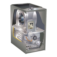
ML180DF unit components are shown in figure 1.The gas
valve, combustion air inducer and burners can be ac
cessed by removing the heating compartment access pan
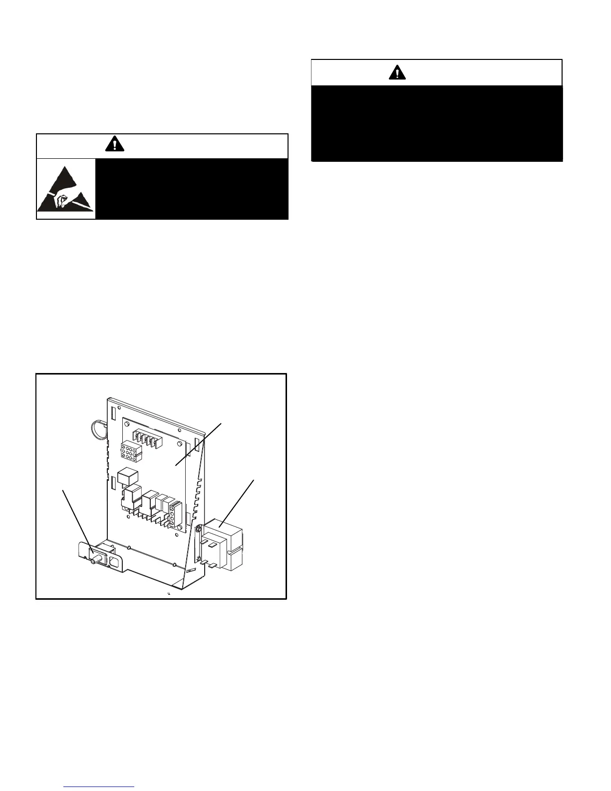
el. Electrical components are in the control box (figure 2)
found in the blower section.
CAUTION
Electrostatic discharge can affect elec
tronic components. Take precautions
to neutralize electrostatic charge by
touching your hand and tools to metal
prior to handling the control.
1. Control Transformer (T1)
A transformer located in the control box provides power to
the low voltage section of the unit. Transformers on all
models are rated 40VA with a 120V primary and a 24V sec
ondary.
2. Door Interlock Switch (S51)
A door interlock switch rated 14A at 125VAC is wired in se
ries with line voltage. When the blower door is removed the
unit will shut down.
FIGURE 2
CONTROL BOX ML180DF
Integrated Control
Transformer
Door
Interlock
Switch
3. Integrated Control (A92)
WARNING
Shock hazard.
Disconnect power before servicing. Control is not
field repairable. If control is inoperable, simply re
place entire control.
Can cause injury or death. Unsafe operation will re
sult if repair is attempted.
The hot surface ignition control system consisting of an in
tegrated control (figure 3 with control terminal designa
tions in tables 1 and 2), flame sensor and ignitor (figure 6).
The integrated control and ignitor work in combination to
ensure furnace ignition and ignitor durability. The inte
grated control, controls all major furnace operations. The
integrated control also features a RED LED for trouble
shooting and two accessory terminals rated at (1) one
amp. See table 3 for troubleshooting diagnostic codes.
The 120 volt ignitor is made from a high strength, silicon
nitride material that provides long life and trouble free
maintenance.
Electronic Ignition (Figure 4)
On a call for heat the integrated control monitors the com
bustion air inducer pressure switch. The control will not be
gin the heating cycle if the pressure switch is closed (by-
passed). Once the pressure switch is determined to be
open, the combustion air inducer is energized. When the
differential in the pressure switch is great enough, the pres
sure switch closes and a 15-second pre-purge begins. If
the pressure switch is not proven within 2-1/2 minutes, the
integrated control goes into Watchguard-Pressure Switch
mode for a 5-minute re-set period.
After the 15-second pre-purge period, the ignitor warms up
for 20 seconds after which the gas valve opens for a 4-sec
ond trial for ignition. The ignitor remains energized for the
first 3 seconds of trial for ignition. If ignition is not proved
during the trial for ignition, the integrated control will try four
more times with an inter purge and warm-up time between
trials of 30 seconds. After a total of five trials for ignition (in
cluding the initial trial), the integrated control goes into
Watchguard-Flame Failure mode. After a 60-minute reset
period, the integrated control will begin the ignition se
quence again.
 Loading...