Page 7
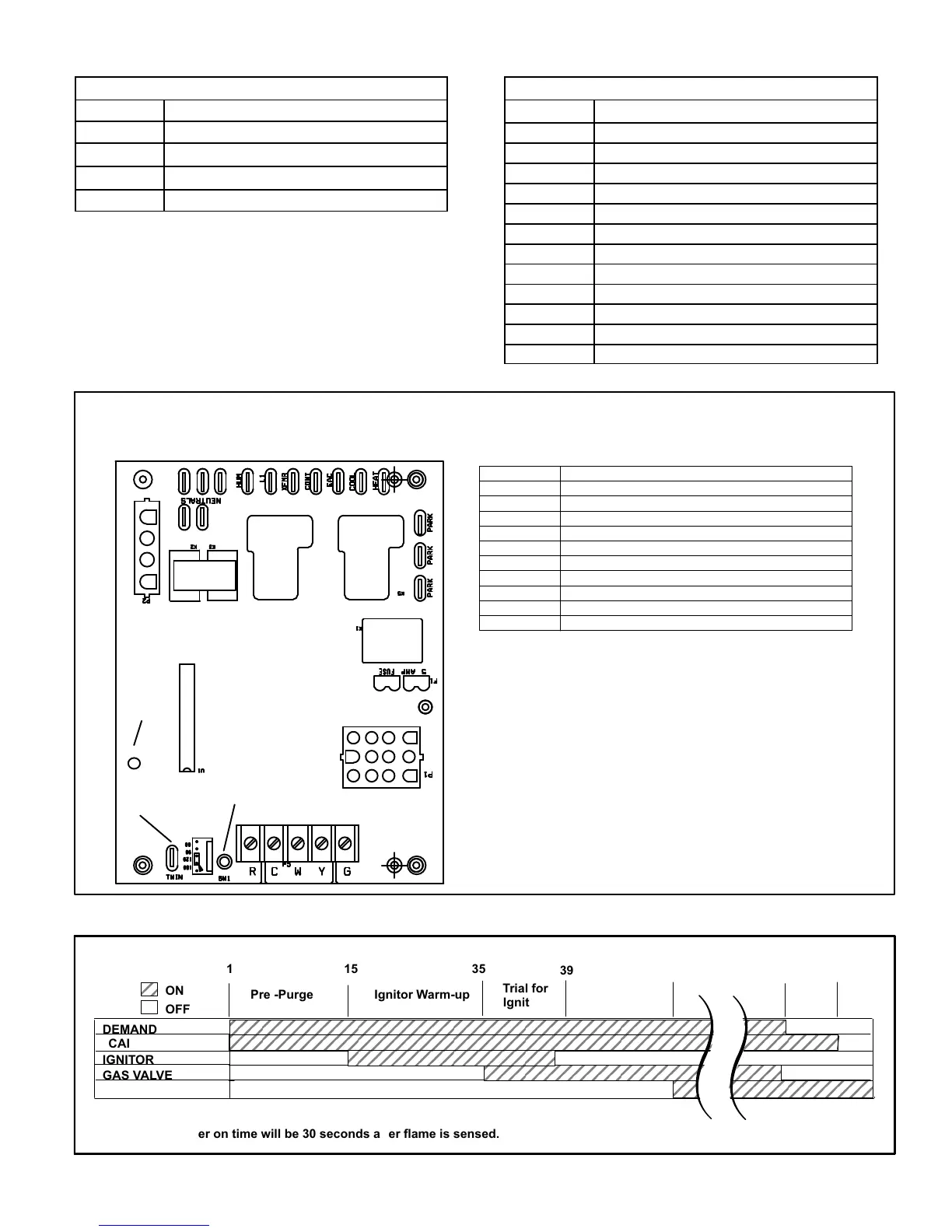
TABLE 1
4-Pin Terminal Designation
PIN # FUNCTION
1 Combustion Air Inducer Line
2
Ignitor Line
3
Combustion Air Inducer Neutral
4
Ignitor Neutral
TABLE 2
12-Pin Terminal Designations
PIN # FUNCTION
1 High Limit Output
2 Sensor
3 24V Line
4 Not Used
5 Rollout Switch Out
6 24V Neutral
7 High Limit Input
8 Ground
9 Gas Valve Common
10 Pressure Switch In
11 Rollout Switch In
12 Gas Valve Out
FIGURE 3
INTEGRATED CONTROL
(Automatic Hot Surface Ignition System)
TERMINAL DESIGNATIONS
HUM
LINE
XFMR
EAC
COOL
HEAT
PARK
CONT
NEUTRALS
Humidifier (120VAC)
Input (120VAC)
Transformer (120VAC)
Indoor Air Qality Accessory Air Cleaner (120VAC)
Blower - Cooling Speed (120VAC)
Blower - Heating Speed (120VAC)
Dead terminals to park alternate spd taps
Continuous blower
Neutral terminals (120VAC)
PUSH BUTTON
LED
TWIN
TWIN
Twinning Terminal (24VAC)
ÉÉÉÉÉÉÉÉÉÉÉÉÉÉÉÉÉÉÉÉÉÉÉÉ
ÉÉÉÉÉÉÉÉÉÉÉÉÉÉÉÉÉÉÉÉÉÉÉÉ
ÉÉÉÉÉÉÉÉÉÉÉÉÉ
ÉÉÉÉÉÉÉÉÉÉÉÉÉ
DEMAND
CAI
GAS VALVE
15
ON
OFF
ÉÉÉÉÉÉÉÉÉÉÉÉÉÉÉÉÉÉÉÉÉÉÉÉÉÉÉ
39
IGNITOR
35
1
Pre -Purge Ignitor Warm-up
Trial for
Ignition
Post
Purge
5 SEC69
*Blower on time will be 30 seconds after flame is sensed. Blower off time will depend on “OFF TIME” Setting.
INDOOR BLOWER
Blower “On”*
Delay
ELECTRONIC IGNITION
FIGURE 4
 Loading...