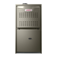
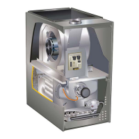
Page 20
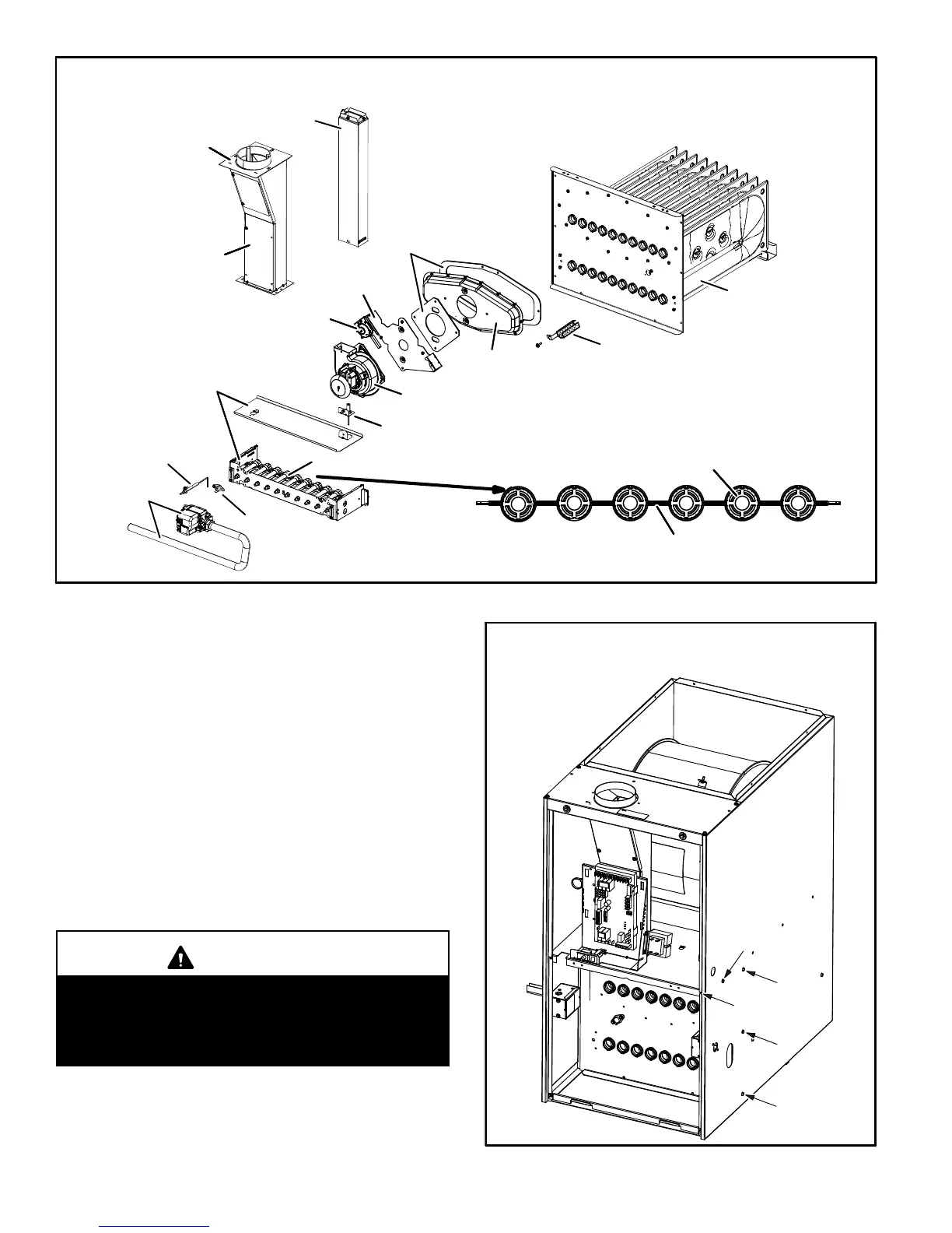
ML180DF BURNER, COMBUSTION AIR INDUCER ASSEMBLY &
HEAT EXCHANGER REMOVAL
FIGURE 17
Gasket
Internal flue pipe
Glue chase
Gasket
Orifice plate
Pressure switch
Collector box
Nox insert
(if applicable)
Heat exchanger
Combustion air inducer
Ignitor
Sensor
Rollout
switch
Burners
Burner box
assembly
Manifold and
Gas valve
Retention rings
Cross over
16- Reinstall burner box, manifold assembly and burner box
cover.
17- Reconnect all wires.
18- Reconnect top cap and vent pipe to combustion air in
ducer outlet.
19- Reconnect gas supply piping.
20- Turn on power and gas supply to unit.
21- Set thermostat and check for proper operation.
22- Check all piping connections, factory and field, for gas
leaks. Use a leak detecting solution or other preferred
means.
CAUTION
Some soaps used for leak detection are corrosive to
certain metals. Carefully rinse piping thoroughly af
ter leak test has been completed. Do not use
matches, candles, flame or other sources of ignition
to check for gas leaks.
23- If a leak is detected, shut gas and electricity off and
repair leak.
24- Repeat steps 22 and 23 until no leaks are detected.
25- Replace access panel.
FIGURE 18
Remove five screws if necessary
(either side of cabinet)
1
2
3
4
5
 Loading...