Page 9
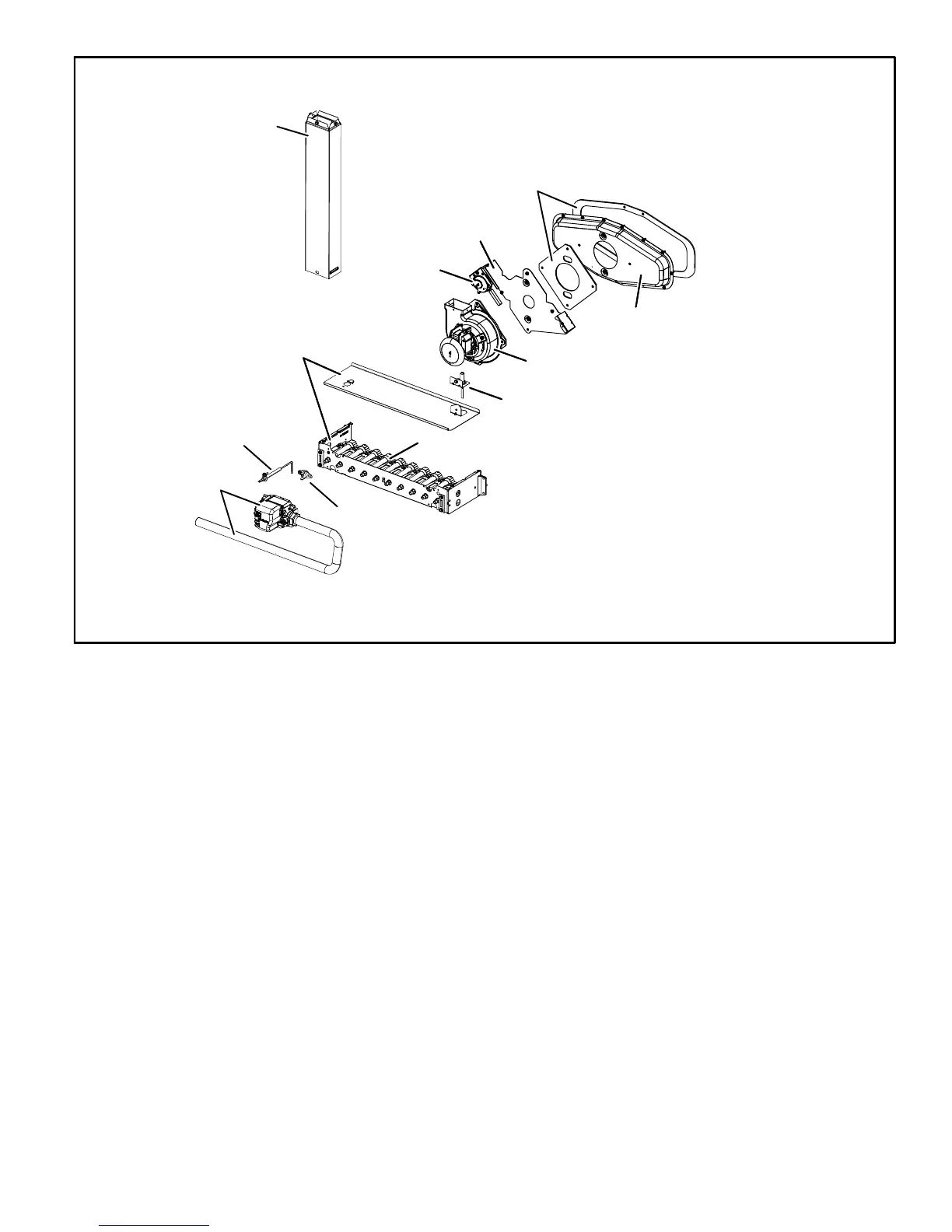
ML180DF HEATING COMPONENTS
FIGURE 6
Internal flue pipe
Gasket
Orifice plate
Pressure switch
Collector box
Combustion air inducer
Ignitor
Sensor
Rollout
switch
Burners
Burner box
assembly
Manifold and
Gas valve
4. Flame Rollout Switch (Figure 6)
Flame rollout switch (S47) is a high temperature limit. The
limit is a N.C. SPST manual‐reset limit connected in series
with the integrated control A92. When S47 senses rollout,
the integrated control immediately stops ignition and
closes the gas valve. If unit is running and flame rollout is
detected, the gas valve will close and integrated control will
be disabled. Rollout can be caused by a blocked heat ex
changer, blocked flue or lack of combustion air. The switch
has a factory setpoint of 210°F and cannot be adjusted. To
manually reset a tripped switch, push the reset button located
on the control.
5. Primary Limit Control
The primary limit on ML180DF units is located in the heating
vestibule panel under the combustion air inducer. When ex
cess heat is sensed in the heat exchanger, the limit will open. If
the limit is open, the integrated control energizes the supply air
blower and closes the gas valve. The limit automatically resets
when unit temperature returns to normal. The switch must re
set within three minutes or the control will go into Watchguard
for one hour. The switch is factory set and cannot be ad
justed. The switch may have a different setpoint for each unit
model number. If limit switch must be replaced, refer to Len
nox ProductZone repair parts list on Lennox DaveNet®.
6. Flame Sensor (Figure 6)
A flame sensor is located on the left side of the burner sup
port. The sensor is mounted on the flame rollout plate and
the tip protrudes into the flame envelope of the left-most
burner. The sensor can be removed for service (clean us
ing steel wool) without removing any part of the burners.
During operation, flame is sensed by current passed
through the flame and sensing electrode. The integrated
control allows the gas valve to remain open as long as
flame signal is sensed.
A microamp DC meter is needed to check the flame signal
on the integrated control.
Flame (microamp) signal is an electrical current which passes
from the integrated control to the sensor during unit operation.
Current passes from the sensor through the flame to ground to
complete a safety circuit.
 Loading...