EasyManua.ls Logo

Lennox ML180UHE Series User Manual

Lennox ML180UHE Series
33 pages
To Next Page IconTo Next Page
Page #1 background imageLoading...
Page #1 background image
Page 1
UNIT INFORMATIONUNIT INFORMATION
Service Literature
©2016 Lennox Industries, Inc.
WARNING
Electric Shock Hazard. Can cause injury
or death. Unit must be properly grounded
in accordance with national and local
codes.
Line voltage is present at all components
when unit is not in operation on units
with single-pole contactors. Disconnect
all remote electric power supplies before
opening access panel. Unit may have
multiple power supplies.
CAUTION
As with any mechanical equipment, contact with
sharp sheet metal edges can result in personal
injury. Take care while handling this equipment and
wear gloves and protective clothing.
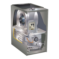
ML180UHE(X) series units are mid-e󰀩ciency gas furnac-
es used for upow or horizontal applications only, man-
ufactured with Lennox Duralok heat exchangers formed
of aluminized steel. ML180UHE(X) units are available in
heating capacities of 44,000 to 132,000 Btuh and cooling
applications 2 to 5 tons. Refer to Engineering Handbook
for proper sizing.
Units are factory equipped for use with natural gas. Kits
are available for conversion to LP/Propane operation.
ML180UHE(X) model units are equipped with a hot sur-
face ignition system. The ML180UHE(X) unit meets the
California Nitrogen Oxides (NOx) Standards and Califor-
nia Seasonal E󰀩ciency requirements.
All units use a redundant gas valve to assure safety shut-
o󰀨 as required by C.S.A. All specications in this manual
are subject to change. Procedures outlined in this manual
are presented as a recommendation only and do not su-
persede or replace local or state codes. In the absence
of local or state codes, the guidelines and procedures
outlined in this manual (except where noted) are recom-
mended only and do not constitute code.
WARNING
Improper installation, adjustment, alteration,
service or maintenance can cause property damage,
personal injury or loss of life. Installation and service
must be performed by a licensed professional HVAC
installer (or equivalent), service agency or the gas
supplier.
TABLE OF CONTENTS
Specications . . . . . . . . . . . . . . . . . . . . . . . . . . . . . Page 2
Blower Data . . . . . . . . . . . . . . . . . . . . . . . . . . . . . . Page 4
Parts Identication . . . . . . . . . . . . . . . . . . . . . . . . . Page 6
I Unit Components . . . . . . . . . . . . . . . . . . . . . . . . Page 7
II Installation . . . . . . . . . . . . . . . . . . . . . . . . . . . . . Page 21
III Start Up . . . . . . . . . . . . . . . . . . . . . . . . . . . . . . Page 21
IV Heating System Service Checks . . . . . . . . . Page 21
V Typical Operating Characteristics . . . . . . . . . Page 26
VI Maintenance . . . . . . . . . . . . . . . . . . . . . . . . . . Page 26
VII Wiring and Sequence of Operation . . . . . . Page 29
ML180UHE(X)
Corp 1120-L4
Revised 10-2017
ML180UHE(X) SERIES UNITS

Other manuals for Lennox ML180UHE Series

Question and Answer IconNeed help?

Do you have a question about the Lennox ML180UHE Series and is the answer not in the manual?

Lennox ML180UHE Series Specifications

General IconGeneral
ModelML180UHE Series
TypeGas Furnace
AFUE Rating80%
StagesSingle-Stage
Ignition TypeHot Surface Ignition
Cabinet TypeUpflow/Horizontal
Heat Exchanger MaterialAluminized Steel
Voltage115V
Cabinet ConstructionHeavy-Gauge Steel
Blower MotorMulti-Speed
Fuel TypeNatural Gas
Maximum External Static Pressure0.5 in. WC

Summary

SPECIFICATIONS

OPTIONAL ACCESSORIES - ORDER SEPARATELY

Night Service Kit

Kit for specific service needs.

Venting

Components for exhaust and ventilation.

Gas Heat Accessories

Accessories for gas heating functionality.

High Altitude

Information for high altitude installations.

BLOWER DATA

PARTS ARRANGEMENT

I-UNIT COMPONENTS

Electrostatic Discharge (ESD) Precautions

Safety procedures for handling electronic components.

FAN TIME CONTROL

HEATING COMPONENTS

Flame Rollout Switches

High temperature limit switches for safety.

Primary Limit Control

Over-temperature limit for heat exchanger.

Flame Sensor

Detects flame presence for burner operation.

GAS VALVE OPERATION

COMBUSTION AIR INDUCER

IGNITOR AND CHECKS

COMBUSTION AIR INDUCER PRESSURE SWITCH

MULTIPLE VENTING

BLOWER MOTOR

MOTOR MODULE REPLACEMENT

II- PLACEMENT AND INSTALLATION

III- START-UP

Heating Start-Up Procedure

Steps for safely starting the furnace in heating mode.

IV-HEATING SYSTEM SERVICE CHECKS

CSA Certification

Compliance with safety standards.

Gas Piping Requirements

Guidelines for gas supply line installation.

Gas Piping Testing

Procedures for checking gas connections and leaks.

GAS PRESSURE ADJUSTMENT

SUPPLY AND MANIFOLD PRESSURE MEASUREMENT

PROPER COMBUSTION ANALYSIS

HIGH ALTITUDE CONSIDERATIONS

GROUND AND VOLTAGE CHECKS

V-TYPICAL OPERATING CHARACTERISTICS

Blower Operation and Adjustment

Setting and adjusting blower speed and timing.

Temperature Rise Specifications

Understanding and setting temperature rise.

External Static Pressure Measurement

Measuring static pressure for airflow adjustment.

VI-MAINTENANCE

VII- WIRING AND SEQUENCE OF OPERATION

Wiring Diagram

Schematic showing electrical connections of unit components.

Heating Sequence of Operation

Detailed operational steps for heating mode.

Heating Sequence Continued

Continuation of heating operational steps and error codes.

Cooling Sequence of Operation

Operational steps and error conditions for cooling mode.

Continuous Fan Sequence

Operation logic for continuous fan mode.

Related product manuals