Page 13
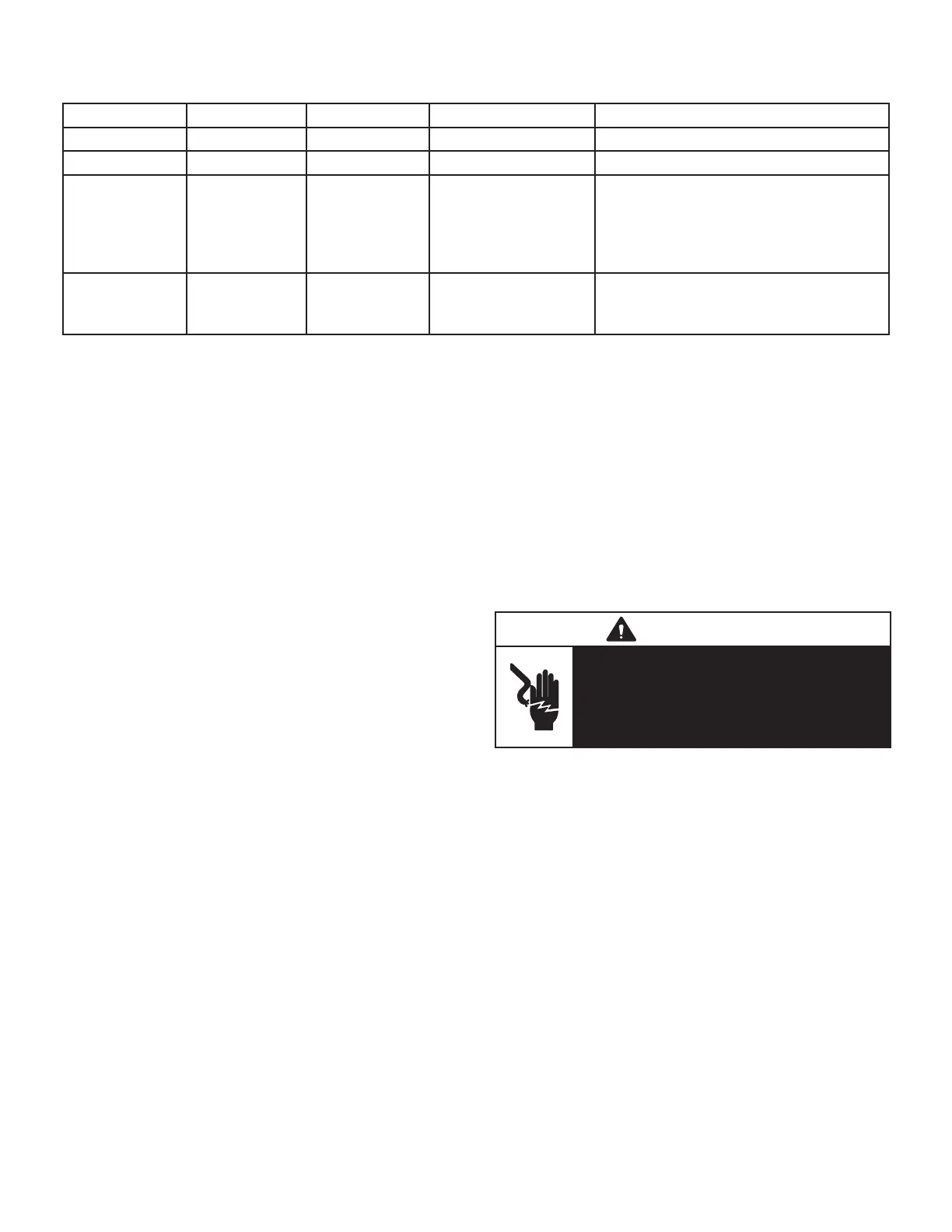
TABLE 5
Nidec / Emerson Motor Only
PW LED RX LED TX LED Motor Blower Action
O Blink Blink Not Rotating Normal
Blink Blink Blink Rotating Normal. PW blink is 100cfm/blink
Blink O Blink Not Rotating
Verify 16X4W and motor control hp
match. Verify power to motor control.
Turn o power for 1 minute then restart.
If motor still does not rotate replace the
controller.
O O O Not Rotating
Verify power to the 16X4W. Turn o
power then restart. If LED’s are still out,
replace controller.
Motor rpm is continually adjusted internally to maintain
constant cfm. The controller monitors the static work
load on the motor and motor amp-draw to determine the
amount of rpm adjustment. Blower rpm may be adjusted
any amount in order to maintain a constant cfm as shown
in Blower Ratings Tables. The cfm remains relatively sta-
ble over a broad range of static pressure. Since the blower
constantly adjusts rpm to maintain a specied cfm, motor
rpm is not rated. Hence, the terms “cool speed” , “heat
speed ” or “speed tap” in this manual, on the unit wiring
diagram and on blower B3, refer to blower cfm regardless
of motor rpm.
The unit control indicates the desired cfm. The blower will
maintain the desired cfm as long as external static pres-
sure does not exceed 0.8”. If the system exceeds this
amount, the blower may enter a “cut back”, mode wherein
it then slows down to protect itself from electrical damage.
During this “cut back” mode the unit control will still indi-
cate the same desired cfm regardless of actual motor rpm.
When Harmony is used, speed taps are overridden and
a PWM signal generated by the Harmony controller con-
tinuously varies motor speed based upon zone demands.
Initial Power Up
When line voltage is applied to B3, there will be a large
inrush of power lasting less than 1/4 second. This inrush
charges a bank of DC lter capacitors inside the controller.
If the disconnect switch is bounced when the disconnect is
closed, the disconnect contacts may become welded. Try
not to bounce the disconnect switch when applying power
to the unit.
Motor Start-Up
When B3 begins start-up, the motor gently vibrates back
and forth for a moment. This is normal. During this time
the electronic controller is determining the exact position
of the rotor. Once the motor begins turning, the controller
slowly eases the motor up to speed (this is called “soft-
start”). The motor may take as long as 10-15 seconds to
reach full speed
If the motor does not reach 200rpm within 13 seconds,
the motor shuts down. Then the motor will immediately at-
tempt a restart. The shutdown feature provides protection
in case of a frozen bearing or blocked blower wheel. The
motor may attempt to start eight times. If the motor does
not start after the eighth try, the controller locks out. Reset
controller by momentarily turning o power to unit.
The DC lter capacitors inside the controller are connect-
ed electrically to the speed tap wires. The capacitors take
approximately 5 minutes to discharge when the discon-
nect is opened. For this reason it is necessary to wait at
least 5 minutes after turning o power to the unit before
attempting to change speed taps.
DANGER
Disconnect power from unit and wait at least
ve minutes to allow capacitors to discharge
before attempting to adjust motor speed tap
settings. Failure to wait may cause personal
injury or death.
External Operation (Speed Tap Priority)
FIGURE 9 and FIGURE 10 shows the two quick-con-
nect jacks (J48 and J49) which connect the motor to the
ML296DFV. Jack J48 is the power plug and jack J49 con-
nects the unit controls to the motor.
Jack J48 is the power plug. Line voltage must be applied
to J48 pins 4 and 5 in order for the motor to operate. When
using 120VAC pins 1 and 2 must be jumpered. Jack J49
connects the unit controls to the motor. The motor assigns
priority to J49 pin 2 so that if a call for cooling and a call
for heating are concurrent, heating call overrides and the
blower operates on high speed heating tap.
 Loading...