Page 12
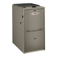
Power Choke
(5 Ton Only)
Blower Motor
(B3)
To Remove Blower From Unit: Remove Bolts and
Wiring Jackplugs. Then Slide Out Front of Unit.
FIGURE 4
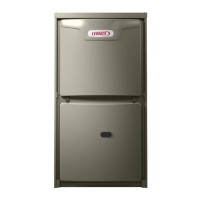
Blower Motor (B3)
Blower motors are manufactured by GenTeq and Nidec.
See FIGURE 6 and FIGURE 7. Motors operate the same
and are only dierent in physical appearance. They are
both three-phase, electronically controlled DC brushless
motors (controller converts single-phase AC to three-
phase DC), with a permanent magnet type rotor. Because
these motors have a permanent magnet rotor it does not
need brushes like conventional DC motors.
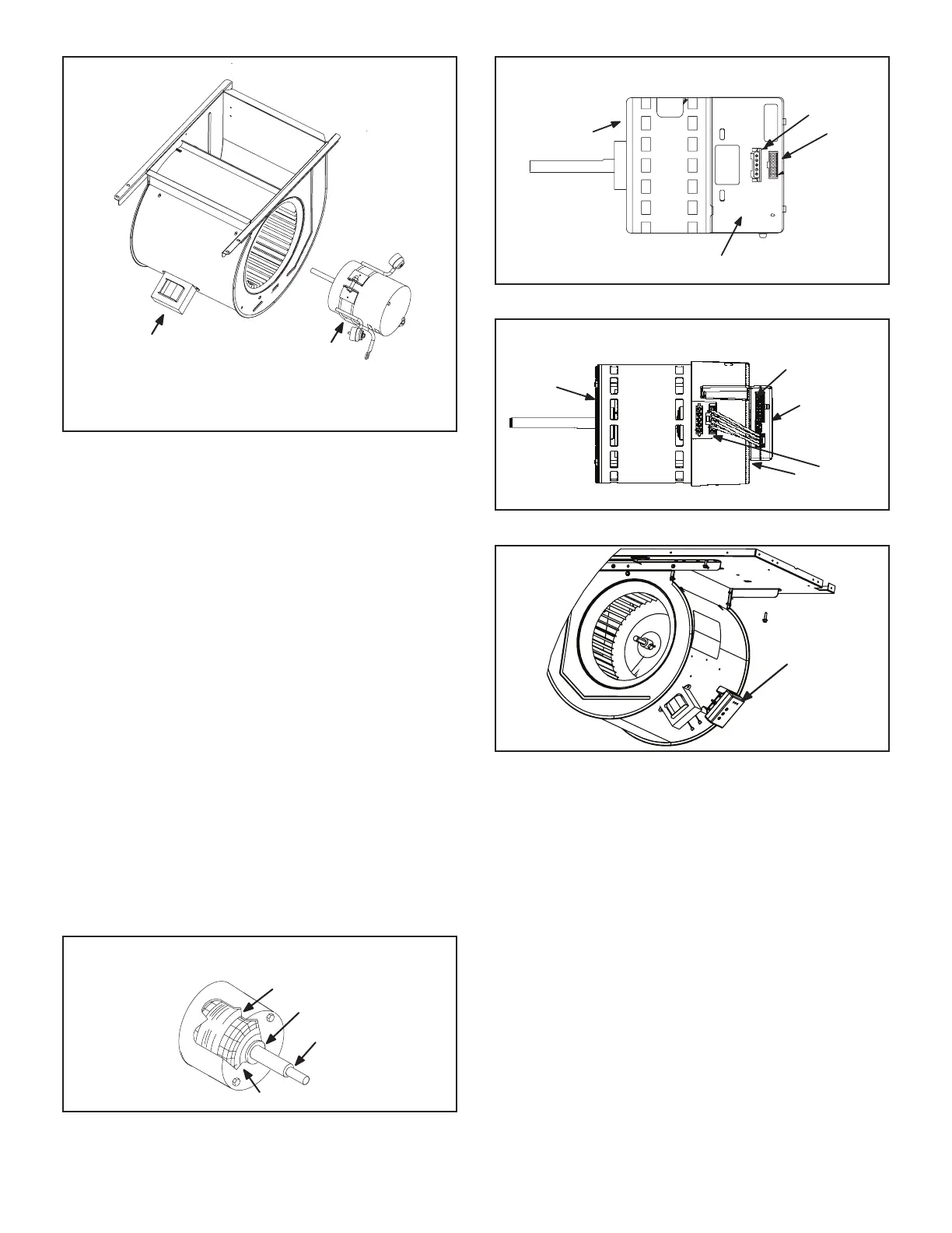
Internal components for both manufactured motors are
similarand shown in FIGURE 5. The stator windings are
split into three poles which are electrically connected to
the controller. This arrangement allows motor windings to
turn on and o in sequence by the controller.
A solid-state controller is attached to the motor. The con-
troller is primarily an AC to DC converter. Converted DC
power is used to drive the motor. The controller contains a
microprocessor which monitors varying conditions inside
the motor (such as motor workload). The controller on the
NIDEC / Emerson motor includes the 16X4W control with
three LED’s PW, RX and TX located on the face for trou-
bleshooting. FIGURE 7 shows the location of the 16X4W
and TABLE 5 the LED codes. The 16X4W may be located
on the indoor blower housing on some models (FIGURE
8).
STATOR
(WINDINGS)
OUTPUT
SHAFT
BEARING
FIGURE 5
MOTOR
CONTROLLER
J49
J48
FIGURE 6
NIDEC BLOWER MOTOR B3
MOTOR
CONTROLLER
16X4W
(May located
on the blower
housing)
J48
J49
FIGURE 7
FIGURE 8
The controller uses sensing devices to sense what posi-
tion the rotor is in at any given time. By sensing the posi-
tion of the rotor and then switching the motor windings on
and o in sequence, the rotor shaft turns the blower.
All blower motors use single phase power. An external run
capacitor is not used. The motor uses permanently lubri-
cated ball-type bearings.
Internal Operation
Each time the controller switches a stator winding (FIG-
URE 5) on and o, it is called a “pulse.” The length of
time each pulse stays on is called the “pulse width.” By
varying the pulse width (FIGURE 11), the controller varies
motor speed (called “pulsewidth modulation”). This allows
for precise control of motor speed and allows the motor to
compensate for varying load conditions as sensed by the
controller. In this case, the controller monitors the static
workload on the motor and varies motor rpm in order to
maintain constant airow (cfm).
 Loading...