Page 19
7. Combustion Air Inducer (B6) and Cold End Header
Box
All units use a two-stage combustion air inducer to move
air through the burners and heat exchanger during heat-
ing operation. The blower uses a 120VAC motor.
The motor operates during all heating operation and is
controlled by integrated control control A92. The induc-
er also operates for 15 seconds before burner ignition
(prepurge) and for 5 seconds after the gas valve closes
(postpurge). The inducer operates on low speed during
rststage heat, then switches to high speed for second
stage heat.
NOTE - Each furnace model uses a unique CAI. Refer to
Lennox Repair Parts listing for correct inducer for replace-
ment.
The combustion air inducer is installed on the cold end
header box. The cold end header box is a single piece
made of hard plastic. The box has an internal channel
where the combustion air inducer creates negative pres-
sure at unit start up. The channel contains an orice used
to regulate ow created by the combustion air inducer.
The box has pressure taps for the combustion air induc-
er pressure switch hoses. The pressure switch measures
the pressure dierential across the combustion air inducer
orice or dierence in the channel and the box. If replace-
ment is necessary the gaskets used to seal the box to
the vestibule panel and the combustion air inducer to
the box, must also be replaced.
A proving switch connected to the combustion air inducer
orice plate is used to prove inducer operation. The com-
bustion air inducer orice will be dierent for each model.
See TABLE 7 for orice sizes. The pressure switch mea-
sures the pressure dierential across the combustion air
inducer orice. When the proving switch opens, the fur-
nace control (A92) immediately closes the gas valve to
prevent burner operation.
TABLE 7
ML296UHV(X) Unit C.A.I. Orice Size
-045 0.700
-070 0.920
-090 1.100
-110 1.155
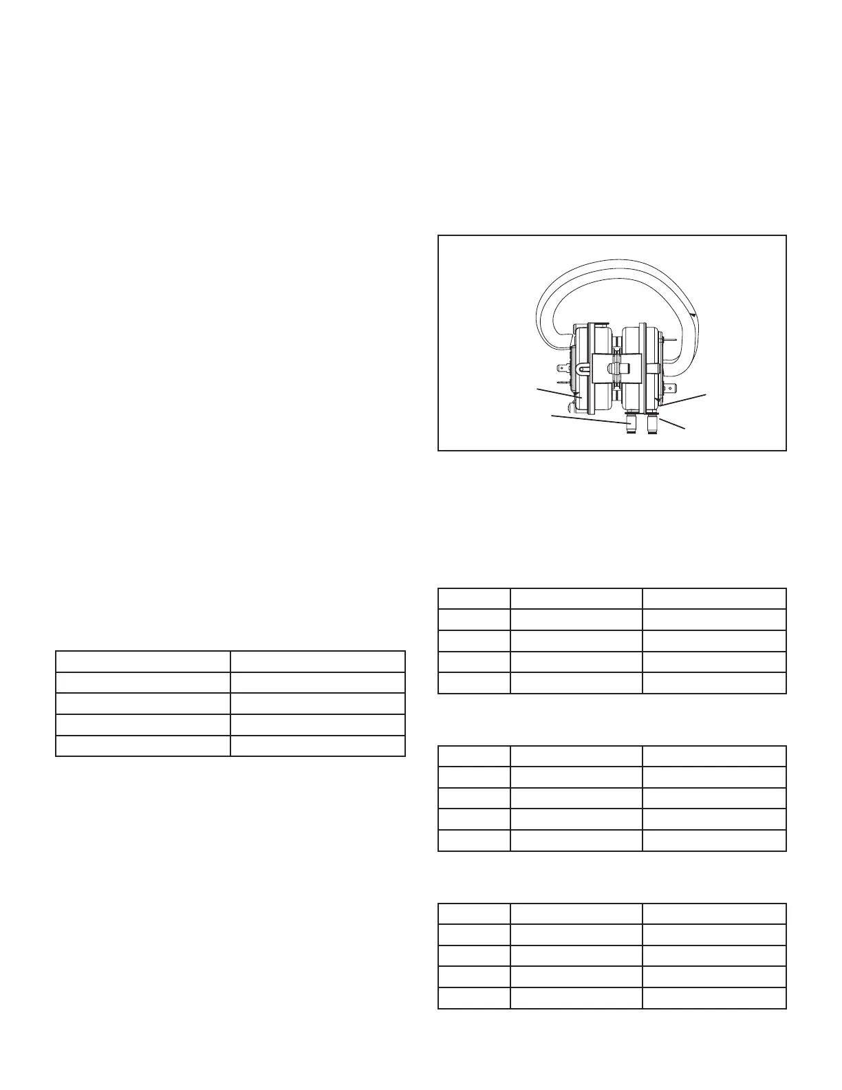
8. Combustion Air Inducer Pressure Switch (S18)
Units are equipped with a dual combustion air pressure
switch (rst and second stage) located on the combustion
air inducer orice bracket. See FIGURE 14. The switch
is connected to the combustion air inducer housing by
means of a exible silicone hose. It monitors negative air
pressure in the combustion air inducer housing.
The switches are a single-pole single-throw proving switch
electrically connected to the integrated control. The pur-
pose of the switch is to prevent burner operation if the
combustion air inducer is not operating or if the ue be-
comes obstructed.On heat demand (rst or second stage)
the switch senses that the combustion air inducer is op-
erating.
It closes a circuit to the integrated control when pressure
inside the combustion air inducer decreases to a certain
set point. Set points vary depending on unit size. See
TABLE 8. The pressure sensed by the switch is nega-
tive relative to atmospheric pressure. If the ue becomes
obstructed during operation, the switch senses a loss of
negative pressure (pressure becomes more equal with at-
mospheric pressure) and opens the circuit to the furnace
control and gas valve. A bleed port on the switch allows
relatively dry air in the vestibule to purge switch tubing, to
prevent condensate build up.
COMBUSTION AIR PRESSURE SWITCH
High Fire Switch
Low Fire Switch
Positive Port
Negative Port
FIGURE 14
NOTE - The switch is factory set and is not eld adjust-
able. It is a safety shut-down control in the furnace and
must not be by-passed for any reason. If switch is closed
or bypassed, the control will not initiate ignition at start up.
TABLE 8
0 - 4500 ft
Unit Set Point Low Heat Set Point High Heat
-045 0.40 0.70
-070 0.50 0.85
-090 0.50 0.85
-110
0.50 0.90
TABLE 9
4501 - 7500 ft
Unit Set Point Low Heat Set Point High Heat
-045 0.35 0.55
-070 0.45 0.75
-090 0.50 0.85
-110 0.45 0.81
TABLE 10
4501 - 7500 ft
Unit Set Point Low Heat Set Point High Heat
-045 0.35 0.55
-070 0.45 0.75
-090 0.50 0.85
-110 0.45 0.81
 Loading...