Page 48
WARNING
The blower access panel must be securely in place
when the blower and burners are operating. Gas
fumes, which could contain carbon monoxide, can
be drawn into living space resulting in personal
injury or death.
IMPORTANT
If a higheciency lter is being installed as part of
this system to ensure better indoor air quality, the
lter must be properly sized. Higheciency lters
have a higher static pressure drop than
standardeciency glass/foam lters. If the pressure
drop is too great, system capacity and performance
may be reduced. The pressure drop may also cause
the limit to trip more frequently during the winter and
the indoor coil to freeze in the summer, resulting in
an increase in the number of service calls.
Before using any lter with this system, check the
specications provided by the lter manufacturer
against the data given in the appropriate Lennox
Product Specications bulletin. Additional
information is provided in Service and Application
Note ACC002 (August 2000).
TABLE 23
Cabinet Width Minimum Filter Size
17-1/2”
16 x 25 x 1(1)
21”
Exhaust and air intake pipes
Check the exhaust and air intake pipes and all connec-
tions for tightness and to make sure there is no blockage.
NOTE - After any heavy snow, ice or frozen fog event the
furnace vent pipes may become restricted. Always check
the vent system and remove any snow or ice that may be
obstructing the plastic intake or exhaust pipes.
Electrical
1 - Check all wiring for loose connections.
2 - Check for the correct voltage at the furnace (furnace
operating).
3 - Check amp-draw on the blower motor.
Motor Nameplate__________Actual__________
Winterizing and Condensate Trap Care
1 - Turn o power to the furnace.
2 - Have a shallow pan ready to empty condensate
water.
3 - Remove the clean out cap from the condensate trap
and empty water. Inspect the trap then reinstall the
clean out cap.
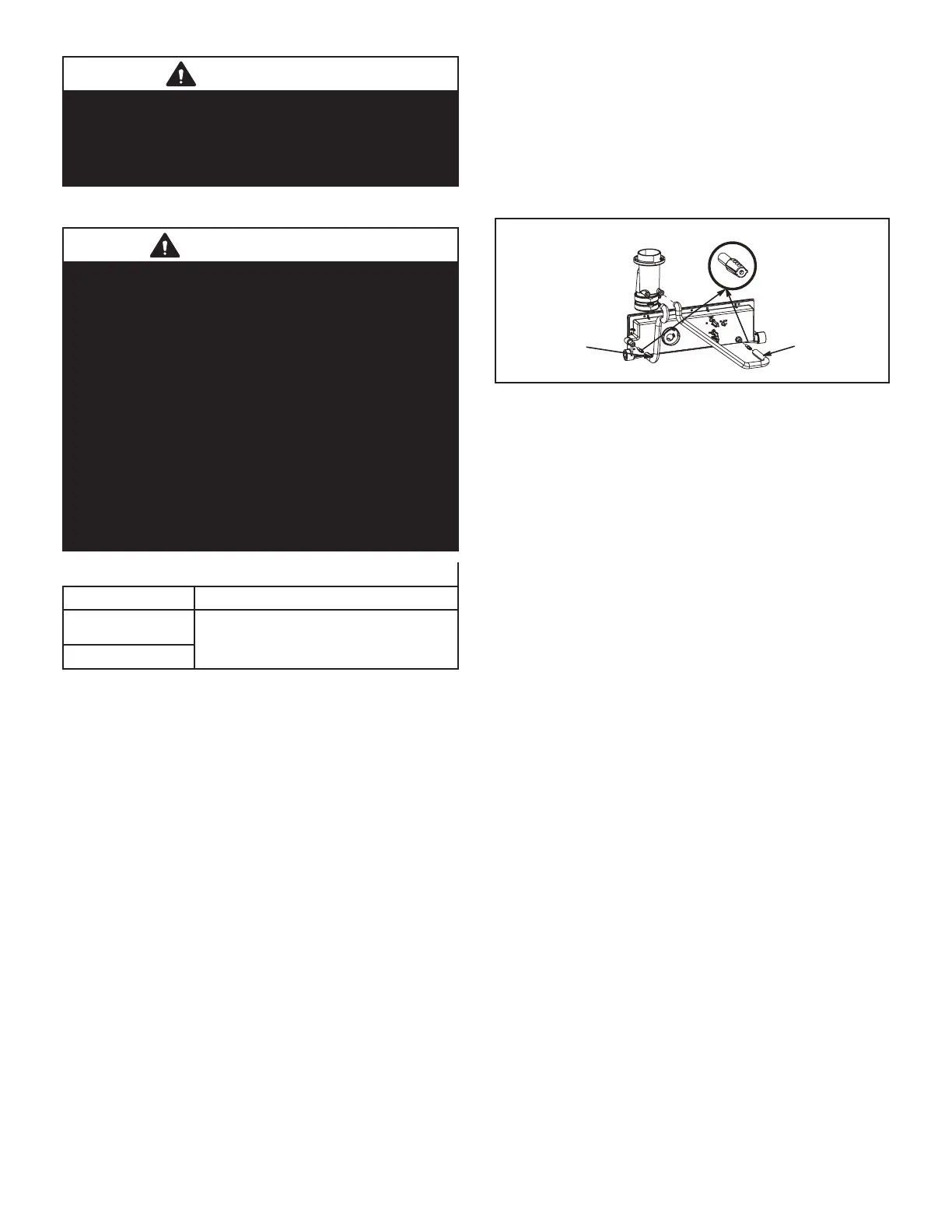
Condensate Hose Screen (FIGURE 55)
Check the condensate hose screen for blockage and
clean if necessary.
1 - Turn o power to the unit.
2 - Remove hose from cold end header box. Twist and
pull screen to remove.
3 - Inspect screen and rinse with tap water if needed.
4 - Reinstall screen and turn on power to unit.
Hose
Hose
FIGURE 55
Cleaning Heat Exchanger
If cleaning the heat exchanger becomes necessary, follow
the below procedures and refer to gure 1 when disas-
sembling unit. Use papers or protective covering in front of
furnace while removing heat exchanger assembly.
1 - Turn o electrical and gas supplies to the furnace.
2 - Remove the furnace access panels.
3 - Disconnect the 2 wires from the gas valve.
4 - Remove gas supply line connected to gas valve.
Remove the burner box cover (if equipped) and
remove gas valve/manifold assembly.
5 - Remove sensor wire from sensor. Disconnect 2-pin
plug from the ignitor.
6 - Disconnect wires from ame roll-out switches.
7 - Disconnect combustion air intake pipe. It may be
necessar to cut the existing pipe to remove burner
box assembly.
8 - Remove four burner box screws at the vestibule
panel and remove burner box. Set burner box
assembly aside.
NOTE - If necessary, clean burners at this time.
Follow procedures outlined in Burner Cleaning
section.
9 - Loosen the clamps to the exible exhaust coupling.
10 - Disconnect condensate drain line from the cold end
header box.
11 - Disconnect condensate drain tubing from ue
collar. Remove screws that secures the ue collar
into place. Remove ue collar. It may be necessary
to cut the exiting exhaust pipe for removal of the
tting.
12 - Mark and disconnect all combustion air pressure
tubing from cold end header collector box.
13 - Mark and remove wires from pressure switch
assembly. Remove the assembly. Keep tubing
attached to pressure switches.
14 - Disconnect the plug from the combustion air inducer.
Remove two screws which secure combustion air
inducer to collector box. Remove combustion air
inducer assembly. Remove ground wire from vest
panel.
 Loading...