XP-6341 6/10 15Section 2 Installation Instructions
Installer/Customer-Supplied Items:
D One 12-volt battery with a minimum rating of 525 cold
crankingamps(CCA)at0_F.
D Remote harness with pigtail connector
(to connect ATS engine start, if used)
D Gravel or crushed stone
D Concrete mounting pad
D Cables and conduit
D Fuel supply line with shutoff valve and pipe sealant
(provided by fuel supplier)
D Carbon monoxide (CO) detector(s)
Available Accessories:
D Air cleaner restriction indicator
D Battery
D Battery charger
D Battery heater
D Block heater
D Flexible fuel lines
D Maintenance kit (includes filters and belt)
D Natural gas strainer
D Relay kit, includes common fault and auxiliary run
relays
D Remote digital gauge
D Remote harnesses
D Rodent guards
2.2.1 Prepare Site
Choose a location that is at least 0.9 m (3 ft.) from any
building or structure and near the incoming gas service.
Allow a minimum of 2.4 m (8 ft.) clearance beyond the
exhaust end of the generator set. Plan the installation so
that the exhaust end of the generator set is not directed
toward the building or any openings where exhaust gas
could be drawn into the building.
Install carbon monoxide detectors on each level of any
building adjacent to the generator set. Locate the
detectors to adequately warn the building’s occupants of
the presence of carbon monoxide.
1. Obtain a building permit and contact your local
utility companies to mark the locations of
underground pipes and cables.
2. Prepare an area for mounting the generator set.
a. Clear all combustible materials, including
plants and shrubs, building materials, and lawn
furniture, from an area at least 2.4 m (8 ft.)
beyond the exhaust end of the generator set.
b. Spread a 76 mm (3 in.) thick layer of gravel to
support the concrete mounting pad. For the
mounting pad dimensions, see Figure 4-3 or
for weather enclosures or Figure 4-4 for sound
enclosures.
c. Lay a 100 mm (4 in.) thick concrete pad on the
gravel layer. Include mounting bolts and stub-
ups for the fuel supply and electrical conduit.
See Figure 4-3 or Figure 4-4 for the mounting
pad dimensions, mounting bolts, and stub-up
locations.
2.2.2 Mount and Ground Generator Set
1. Place the generator set on the concrete mounting
pad. Secure the generator set with mounting bolts
anchored in the c oncrete pad.
2. Remove the enclosure doors and alternator-end
panel to gain access to the junction box and other
generator set components during installation.
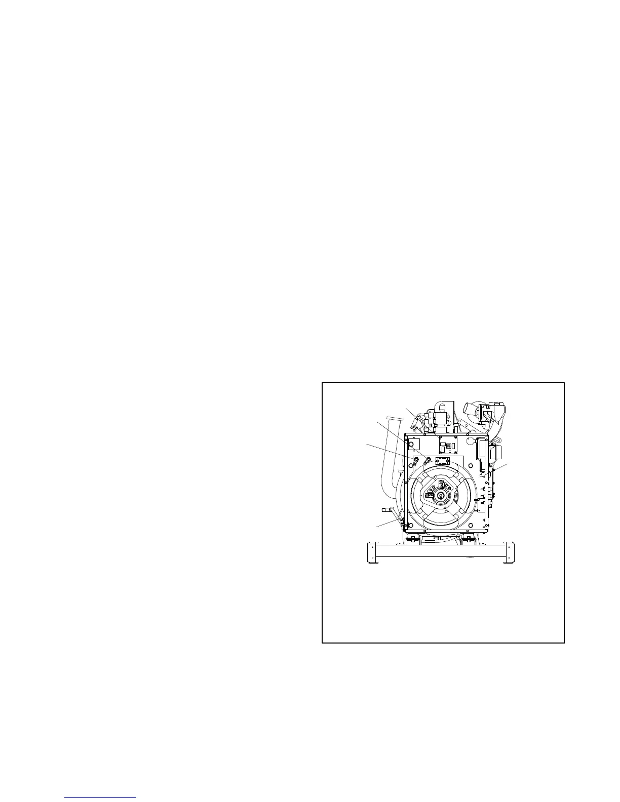
3. Ground the generator set. The grounding method
must comply with NEC and local codes. Connect
the grounding strap to the generator set ground
lug, terminal GRD inside the junction box. See
Figure 2-1.
1. Neutral (L0) connection
2. Ground (GRD) connection
3. Relay interface board (RIB; standard 3--relay board shown)
4. Line circuit breaker
5. Load lead access opening and customer interface connector
4
3
5
2
1
GM39949B--R
Figure 2-1 Generator Set Electrical Connections
(enclosure not shown)
 Loading...