XP-6341 6/10 17Section 2 Installation Instructions
6. Connect the red battery cable to the positive (+)
battery terminal.
7. Connect the black battery cable to the negative (--)
battery terminal.
8. Place the boots over the battery terminals.
9. Plug the battery charger into the 120 VAC power
supply.
2.2.5 Install and Connect Fuel Supply
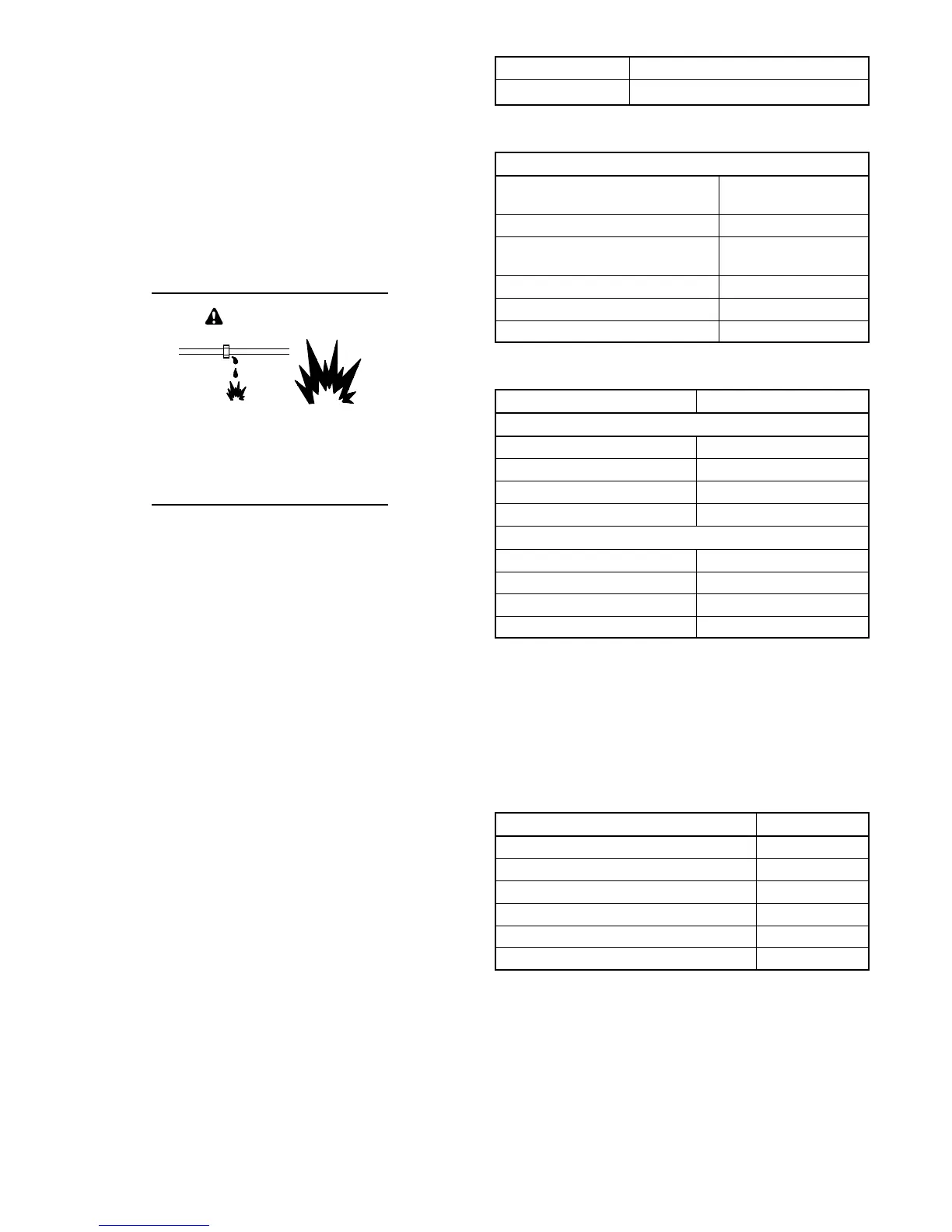
Explosive fuel vapors.
Can cause severe injury or death.
Use extreme care when handling,
storing, and using fuels.
WARNING
The fuel system. Explosive fuel vapors can cause severe
injury or death. Vaporized fuels are highly explosive. Use
extreme care when handling and storing fuels. Store fuels in a
well-ventilated area away from spark-producing equipment
and out of the reach of children. Never add fuel to the tank
while the engine is running because spilled fuel may ignite on
contact with hot parts or from sparks. Do not smoke or permit
flames or sparks to occur near sources of spilled fuel or fuel
vapors. Keep the fuel lines and connections tight and in good
condition. Do not replace flexible fuel lines with rigid lines. Use
flexible sections to avoid fuel line breakage caused by
vibration. Do not operate the generator set in the presence of
fuel leaks, fuel accumulation, or sparks. Repair fuel systems
before resuming generator set operation.
Note: Have the fuel piping and regulator installed by the
fuel supplier. The fuel supply installation must
comply with NFPA and local codes.
1. See F igure 2-2, Figure 2-3, and Figure 2-4 for the
fuel supply requirements. Add up the fuel
requirements for the generator set plus all other
gas-fired equipment fueled by the same supply.
2. Check that the primary regulator and gas meter
have sufficient capacity for the fuel requirements
for the generator set plus all other gas-fired
equipment. Have the fuel supplier install a larger
gas meter, if necessary.
Model Gas Flow Rate, Btu/hr.
RGEN30 450000
Figure 2-2 Gas Flow Rate (natural gas and LP)
Fuel Supply Specifications
Fuel type
LP Gas or Natural
Gas
Fuel supply inlet 3/4-14 NPT
Fuel supply pressure,
oz./in.
2
(in. H
2
O)
4--6 (7--11)
Nominal Fuel Rating, Btu/ft.
3
:
Natural gas 1000
LP vapor 2500
Figure 2-3 Fuel Requirements
Fuel Consumption m
3
/hr. (cfh)
Natural Gas at % Load
100% 12.7 (450)
75% 10.6 (375)
50% 8.5 (300)
25% 6.4 (225)
LP Gas at % Load
100% 5.1 (180)
75% 4.2 (150)
50% 3.4 (120)
25% 2.5 (90)
Figure 2-4 Fuel Consumption
3. Measure the pipe length from the primary gas
pressure regulator to the pipe connection on the
generator set fuel inlet. Add 2.4 m (8 ft.) to the
measured length for each 90 degree elbow. Use
the pipe size indicated in Figure 2-5 for the total
length of pipe.
Maximum Pipe Length m (ft.) Pipe Size
6.1 (20) 1 1/4 in. NPT
9.1 (30) 1 1/4 in. NPT
18.3 (60) 1 1/2 in. NPT
30.5 (100) 1 1/2 in. NPT
45.7 (150) 2in.NPT
61.0 (200) 2in.NPT
Figure 2-5 Fuel Pipe Sizes
 Loading...