XP-6341 6/1018 Section 2 Installation Instructions
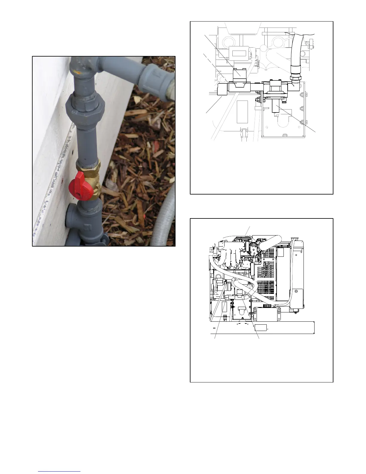
Have your fuel supplier install a manual fuel shutoff
valve and rigid gas piping. Bring the pipe to within
254 mm (10 in.) of the generator set fuel inlet
location. See Figure 2-6.
Figure 2-6 Manual Fuel Shutoff Valve (outdoor
installation shown)
2.2.6 Generator Set Fuel Systems
Compare your fuel system to Figure 2-7 and Figure 2-8.
D Generator sets with serial numbers below 2272938,
built before November 2, 2009, use the secondary
regulator shown i n Figure 2-7.
D Generator sets with serial numbers above 2272938,
built after November 2, 2009, use the fuel system
shown in Figure 2-8, which has an integrated
electronic pressure regulator (IEPR) mounted above
the engine.
Note: The integrated electronic pressure regulator
(IEPR) and air/fuel mixer are specially
calibrated emission-control devices. Do not
adjust the IEPR or the air/fuel mixer.
1
GM39949D--R
1. Fuel solenoid valve (2 required for UL2200)
2. 1/4 in. port for inlet fuel pressure (back side)
3. Secondary regulator (shown pointing down for LP)
4. Fuel supply connection
3
4
2
Note: UL 2200-listed units include a second fuel valve.
Figure 2-7 Early Model Fuel System (LP gas setup
shown)
3
Note: UL 2200-listed units include a second fuel valve. See
Figure 2-9.
2
ADV-7692
1
1. Integrated electronic pressure regulator (IEPR)
2. Fuel solenoid valve
3. Fuel supply connection, 3/4 NPT
Figure 2-8 Later Model Fuel System with IEPR
 Loading...