XP-6341 6/1026 Section 3 Controller
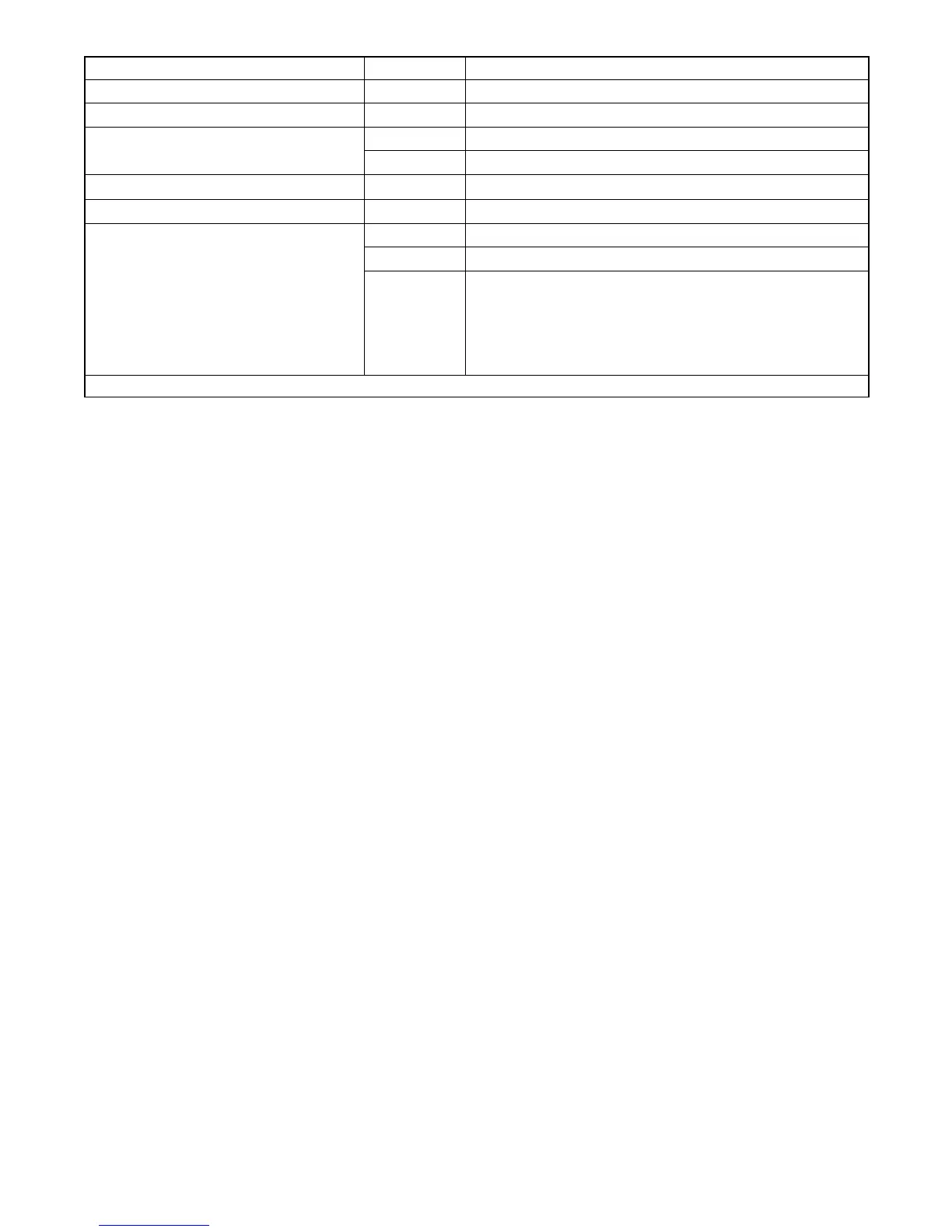
Parameter Setting Definition
Unit’s system voltage and frequency Uu01 Single phase, 3 wire, 60 Hz, 120/240 VAC
Unit configuration Uc01 Standby
Engine type
Ec06 RGEN30 (serial numbers below 2272938) *
Ec11 RGEN30 (serial numbers above 2272938) *
Engine data input types Ed01
RGEN30
Battery Voltage Bt12 Battery voltage 12 VDC
Communications
Cn00 No CAN communications, 48-hour power down
Cn01 J1939 (use for Remote Digital Gauge), no power down
Cn06 *
Enables J1939 communications and 1-hour controller power
down after engine stop for either:
a. Remote start/stop switch
b. Automatic transfer switch
c. Remote Digital Gauge with remote start/stop switch and
replacement harness
* See Section 2.2.6.
Figure 3-1 Configuration Parameters
Follow the instructions in Figure 3-2 to enter the
configuration mode while the engine is not running and
then step through the parameters. Use the up (
∧) and
down (
∨) arrow buttons to select the appropriate setting
for the application.
Note: Be sure to save your settings before exiting the
configuration mode. See Figure 3-4. The
controller reverts to the last saved settings when
the master switch is moved to the OFF/RESET
position.
Voltage/frequency setting (Uu). Set the system
voltage and frequency to the value shown in Figure 3-1.
Note: This parameter sets the nominal system voltage
and frequency. To adjust the output (measured)
voltage, see Section 3.4.
Unit configuration (Uc). This parameter sets the
generator set type: marine, standby, or mobile.
Engine configuration (Ec). The engine configuration
must match the generator set engine type. The Ec
setting for units built after November 2, 2009, is diffferent
than the setting for earlier units. See Figure 3-1 and
Section 2.2.6.
Advanced configuration mode (Adnc). The data
input types, battery voltage, and communications
setting can be changed in the advanced configuration
mode. Press the up arrow button when Adnc is
displayed to enter the advanced configuration mode.
SeeFigure3-3.
Engine data input types (Ed). This setting defines the
type of senders used on the generator set engine.
Battery voltage (Bt). This setting toggles between 12
and 24 VDC for the engine starting battery voltage. The
RGEN30 uses a 12-volt battery, Bt12.
Communications setting (Cn). This setting allows the
user to set the controller for communication with
optional meters. The RGEN30 is factory-set for no CAN
communications, Cn00. Change this setting to Cn01 or
Cn06 if an optional Remote Digital Gauge is used. See
Figure 3-1.
 Loading...