Page 14
Use PVC primer and solvent cement or ABS solvent cement meeting ASTM specications, refer to TABLE 5. As an alter-
nate, use all purpose cement, to bond ABS, PVC, or CPVC pipe when using ttings and pipe made of the same materials.
Use transition solvent cement when bonding ABS to either PVC or CPVC. Low temperature solvent cement is recom-
mended. Metal or plastic strapping may be used for vent pipe hangers. Uniformly apply a liberal coat of PVC primer for
PVC.
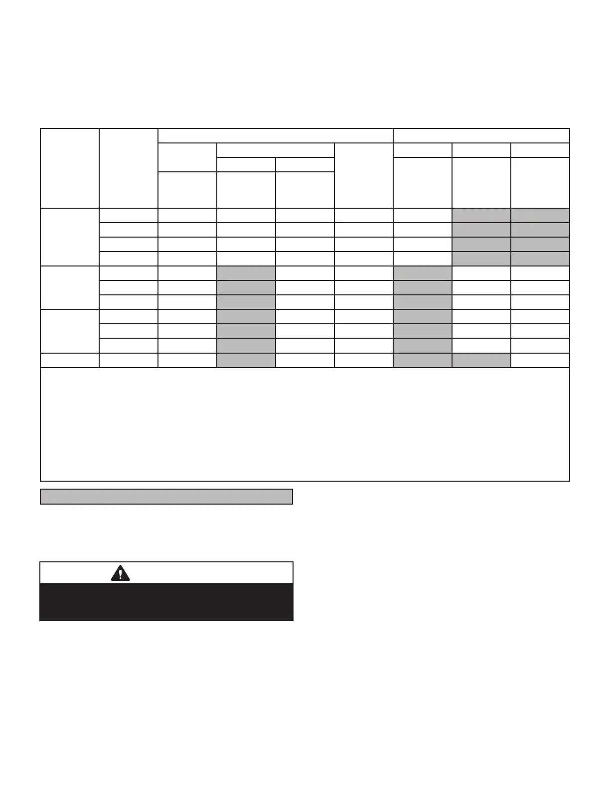
TABLE 6
OUTDOOR TERMINATION USAGE*
Input Size
Vent Pipe
Dia. in.
STANDARD CONCENTRIC
Flush Mount
Kit
Wall Kit
Field
Fabricated
1-1.2 inch 2 inch 3 inch
2 inch 3 inch
71M80 (US)
4
44W92
(CA)
69M29 (US)
4
44W92
(CA)
60L46 (US)
4
44W93
(CA)
51W11 (US)
51W12
(CA)
22G44 (US)
4
30G28 (CA)
44J40 (US)
4
81J20 (CA)
070
6
1-1/2
3
YES YES
1
YES
5
YES
2
YES
2
3
YES YES
1
YES
5
YES
2
YES
2-1/2
3
YES YES
1
YES
5
YES
2
YES
3
3
YES YES
1
YES
5
YES
2
YES
090
2
3
YES YES
5
YES YES YES
2-1/2
3
YES YES
5
YES YES YES
3
3
YES YES
5
YES YES YES
110
2 YES YES
5
YES YES YES
2-1/2 YES YES
5
YES YES YES
3 YES YES
5
YES YES YES
135 3 YES YES
5
YES YES
NOTE - Standard Terminations do not include any vent pipe or elbows external to the structure. Any vent pipe or elbows external to the structure must be included in total
vent length calculations. See vent length tables.
* Kits must be properly installed according to kit instructions.
1Requires eld-provided outdoor 1-1/2” exhaust accelerator.
2Concentric kits 71M80 and 44W92 include 1-1/2 in. outdoor accelerator, when used with 070 input models. When 1-1/2 in. pipe is used it must transition to 2 in. pipe with
the concentric kit.
3 Flush mount kits 51W11 and 51W12 includes 1-1/2 in. outdoor exhaust accelerator, required when used with 070 and 090 input models. When 1-1/2 in. pipe is used it
must transition to 2 in. pipe with the ush mount kit.
4 Termination kits 30G28, 44W92, 4493 and 81J20 are certied to ULC S636 for use in Canada only.
5 See table 7 for vent accelerator requirements.
6 2 in. to 1-1/2 in.
eld provided reducer required.
Joint Cementing Procedure
All cementing of joints should be done according to the specications outlined in ASTM D 2855.
NOTE - A sheet metal screw may be used to secure the
intake pipe to the connector, if desired. Use a drill or self
tapping screw to make a pilot hole.
DANGER
Fumes from PVC glue may ignite during system check.
Allow fumes to dissipate for at least 5 minutes before
placing unit into operation.
1 - Measure and cut vent pipe to desired length.
2 - Debur and chamfer end of pipe, removing any
ridges or rough edges. If end is not chamfered,
edge of pipe may remove cement from tting socket
and result in a leaking joint.
NOTE - Check the inside of vent pipe thoroughly for any
obstruction that may alter furnace operation.
3 - Clean and dry surfaces to be joined.
4 - Test t joint and mark depth of tting on outside of
pipe.
5 - Uniformly apply a liberal coat of PVC primer for
PVC or use a clean dry cloth for ABS to clean inside
socket surface of tting and male end of pipe to
depth of tting socket.
6 - Promptly apply solvent cement to end of pipe and
inside socket surface of tting. Cement should be
applied lightly but uniformly to inside of socket. Take
care to keep excess cement out of socket. Apply
second coat to end of pipe.
NOTE - Time is critical at this stage. Do not allow prim-
er to dry before applying cement.
 Loading...


