Page 33
Electrical
ELECTROSTATIC DISCHARGE (ESD)
Precautions and Procedures
CAUTION
Electrostatic discharge can aect electronic components.
Take precautions during furnace installation and service
to protect the furnace’s electronic controls. Precautions
will help to avoid control exposure to electrostatic
discharge by putting the furnace, the control and the
technician at the same electrostatic potential. Neutralize
electrostatic charge by touching hand and all tools on an
unpainted unit surface, such as the gas valve or blower
deck, before performing any service procedure.
WARNING
Electric Shock Hazard. Can cause injury or
death. Unit must be properly grounded in
accordance with national and local codes.
WARNING
Fire Hazard. Use of aluminum wire with this product may
result in a re, causing property damage, severe injury
or death. Use copper wire only with this product..
CAUTION
Failure to use properly sized wiring and circuit breaker
may result in property damage. Size wiring and circuit
breaker(s) per Product Specications bulletin (EHB) and
unit rating plate.
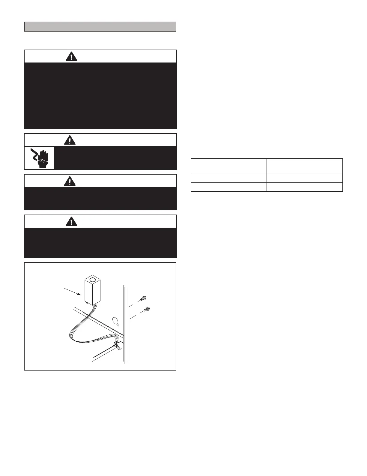
INTERIOR MAKE-UP BOX INSTALLATION
MAKE-UP
BOX
Right Side
FIGURE 51
The unit is equipped with a eld make-up box on the left
hand side of the cabinet. The make-up box may be moved
to the right side of the furnace to facilitate installation. If
the make-up box is moved to the right side, clip the wire
ties that bundle the wires together. The excess wire must
be pulled into the blower compartment. Secure the excess
wire to the existing harness to protect it from damage.
See FIGURE 52 and FIGURE 53 for thermostat wiring in
communicating applications. TABLE 15 shows DIP switch
and on-board link settings for non-communicating ther-
mostat applications. Typical wiring schematic is shown in
FIGURE 54.
1 - The power supply wiring must meet Class I
restrictions. Protected by either a fuse or circuit
breaker, select circuit protection and wire size
according to unit nameplate.
NOTE - Unit nameplate states maximum current draw.
See TABLE 12 for maximum over-current protection.
TABLE 12
SL99UHV Model
Maximum Over-Current
Protection Amps
070-36B, 090-36C, 090-48C 15
090-60C, 110-60C, 135-60D 20
2 - Holes are on both sides of the furnace cabinet to
facilitate wiring.
3 - Install a separate (properly sized) disconnect switch
near the furnace so that power can be turned o for
servicing.
4 - Before connecting the thermostat or the power
wiring, check to make sure the wires will be long
enough for servicing at a later date. Remove the
blower access panel to check the length of the wire.
5 - Complete the wiring connections to the equipment.
Use the provided unit wiring and eld wiring diagram
shown in FIGURE 54 and TABLE 15. Use 18-gauge
wire or larger that is suitable for Class II rating for
thermostat connections.
NOTE - Do NOT make a wire connection between
the room thermostat L terminal and the L terminal
of the SLP99UHV integrated control unless this
is a communicating thermostat installation with
a non-communicating outdoor unit.
6 - Electrically ground the unit according to local codes
or, in the absence of local codes, according to the
current National Electric Code (ANSI/NFPA No. 70)
for the USA and current Canadian Electric Code
part 1 (CSA standard C22.1) for Canada. A green
ground wire is provided in the eld make-up box.
7 - One line voltage “EAC” 1/4” spade terminal is
provided on the furnace integrated control. Any
electronic air cleaner or other 120V accessory rated
up to one amp can be connected to this terminal
with the neutral leg
 Loading...


