Page 43
Switches 8 and 9 - Cooling Mode Blower Speed
The unit is shipped from the factory with the DIP switches
positioned for high speed (4) indoor blower motor opera-
tion during the cooling mode. The table below provides the
cooling mode blower speeds that will result from dierent
switch settings. Refer to tables beginning on page 44 for
corresponding cfm values.
TABLE 19
Cooling Mode Blower Speeds
Speed Switch 8 Switch 9
1 - Low On On
2 - Medium Low O On
3 - Medium High On O
4 - High Factory O O
Switches 10 and 11 - Cooling Mode Blower Speed Adjustment
The unit is shipped from the factory with the DIP switches
positioned for NORMAL (no) adjustment. The DIP switch-
es may be positioned to adjust the blower speed by +10%
or -10% to better suit the application. Table 17 provides
blower speed adjustments that will result from dierent
switch settings. Refer to tables beginning on page 44 for
corresponding cfm values.
With switches 10 and 11 set to ON, motor will bypass
ramping proles and all delays and will immediately run
at selected COOLING speed upon a call for cool. LED will
continue to operate as normal. This mode is used to check
motor operation.
TABLE 20
Cooling Mode Blower Speed Adjustment
Adjustment Switch 10 Switch 11
+10% (approx.) On O
Default Cool CFM O O
- 10% (approx.) O On
Motor Test On On
Switches 12 and 13 - Cooling Mode Blower Speed Ramping
Blower speed ramping may be used to enhance dehumid-
ication performance. The switches are factory set at op-
tion A which has the greatest eect on blower motor per-
formance. TABLE 21 provides the cooling mode blower
speed ramping options that will result from dierent switch
settings. The cooling mode blower speed ramping options
are detailed below.
NOTE - The o portion of the selected ramp prole only
applies during heat pump operation in dual fuel applica-
tions.
TABLE 21
Cooling Mode Blower Speed Ramping
Ramping Option Switch 12 Switch 13
A (factory) O O
B On O
C O On
D On On
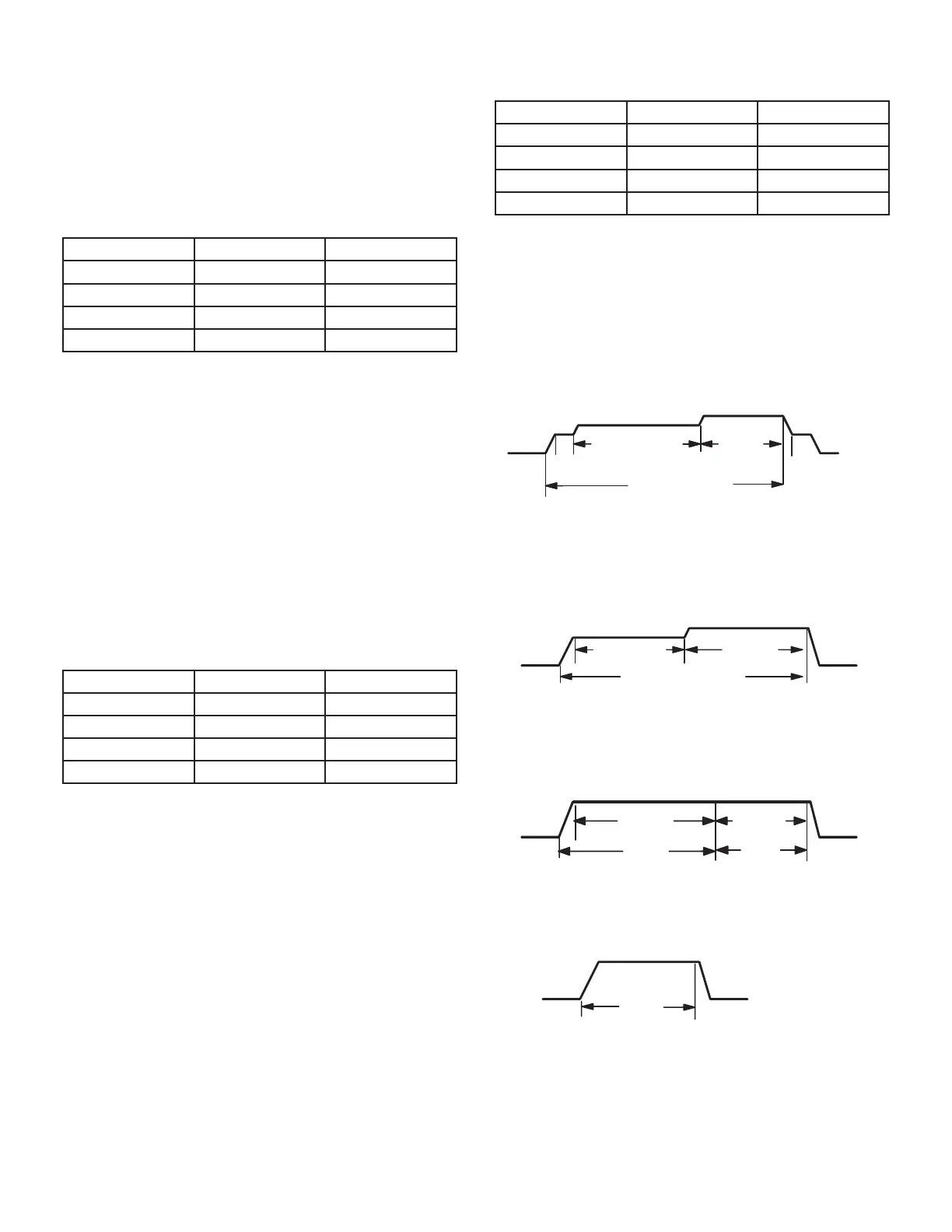
Ramping Option A (Factory Selection)
• Motor runs at 50% for 30 seconds.
• Motor then runs at 82% for approximately 7-1/2 min-
utes.
• If demand has not been satised after 7-1/2 minutes,
motor runs at 100% until demand is satised.
• Once demand is met, motor runs at 50% for 30 sec-
onds then ramps down to stop.
1/2 MIN
50% CFM
COOLING DEMAND
7 1/2 MIN
82% CFM
100%
CFM
1/2 MIN
50% CFM
Ramping Option B
• Motor runs at 82% for approximately 7-1/2 minutes. If
demand has not been satised after 7-1/2 minutes, mo-
tor runs at 100% until demand is satised.
• Once demand is met, motor ramps down to stop.
82%CFM
100% CFM
COOLING DEMAND
7 1/2 MIN
Ramping Option C
• Motor runs at 100% until demand is satised.
• Once demand is met, motor runs at 100% for 45 sec-
onds then ramps down to stop.
OFF
OFF
100% CFM
100% CFM
COOLING DEMAND
45 SEC.
Ramping Option D
• Motor runs at 100% until demand is satised.
• Once demand is met, motor ramps down to stop.
OFFOFF
100% CFM
COOLING
DEMAND
 Loading...


