Page 27
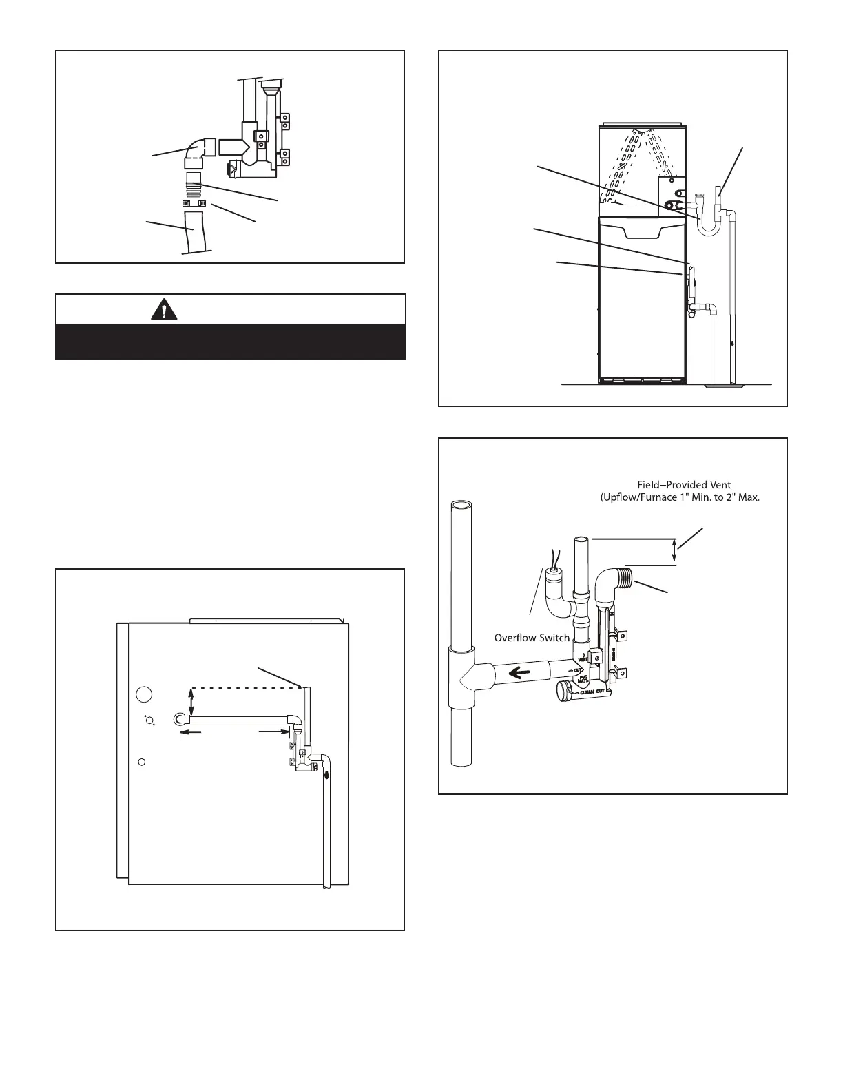
Field Provided Drain Components
Tubing
Hose Clamp
Barbed Fitting
Elbow
FIGURE 40
CAUTION
Do not use copper tubing or existing copper condensate
lines for drain line..
6 - If unit will be started immediately upon completion
of installation, prime trap per procedure outlined in
Unit Start-Up section.
Condensate line must slope downward away from the trap
to drain. If drain level is above condensate trap, conden-
sate pump must be used. Condensate drain line should
be routed within the conditioned space to avoid freezing
of condensate and blockage of drain line. If this is not pos-
sible, a heat cable kit may be used on the condensate
trap and line. Heating cable kit is available from Lennox
in various lengths; 6 ft. (1.8m) - kit no. 26K68 and 24 ft.
(7.3m) - kit no. 26K69.
(Unit shownin upflow position withremote trap)
*5’ max.
To Drain
PVCPipeOnly
FieldProvidedVent
Min.1” AboveCondensate
Drain
Connection
1”
Min.
Trap CanBeInstalleda
Maximum 5’ From Furnac
e
2” Max.
CONDENSATE TRAP LOCATIONS
*Piping from furnace must slope down a
minimum 1/4” per ft. toward trap
FIGURE 41
Furnace With Evaporator
Coil Using A Separate Drain
Condensate
Drain
Connection
Field Provided Vent
(1” min. 2” max. above
condensate connection)
Evaporator drain
line required
(Trap at coil is optional)
FIGURE 42
HorizontalFurnace4” Min.to5” Max.above
condensatedrain connection)
FurnaceCondensate
Drain
Connection
From Evaporator Coil
Optional
Condensate Trap With Optional Overflow Switch
FIGURE 43
 Loading...


