Page 51
9 - Replace the access panel.
10 - Turn on all electrical power to the unit.
11 - Set the thermostat to desired setting.
NOTE - When unit is initially started, steps 1 through 11
may need to be repeated to purge air from gas line.
12 - If the appliance will not operate, follow the
instructions “Turning O Gas to Unit” and call the
gas supplier.
Turning O Gas to Unit
1 - Set the thermostat to the lowest setting.
2 - Turn o all electrical power to the unit if service is to
be performed.
3 - Remove the access panel.
4 - Move the gas valve switch to the OFF position.
5 - Replace the access panel.
Failure To Operate
If the unit fails to operate, check the following:
1 - Is the thermostat calling for heat?
2 - Are access panels securely in place?
3 - Is the main disconnect switch closed?
4 - Is there a blown fuse?
5 - Is the lter dirty or plugged? Dirty or plugged lters
will cause the limit control to shut the unit o.
6 - Is gas turned on at the meter?
7 - Is the manual main shut-o valve open?
8 - Is the gas valve turned on?
9 - Is the unit ignition system in lock out? If the unit
locks out again, inspect the unit for blockages.
10 - Is blower harness connected to ignition control?
Furnace will not operate unless harness is
connected.
Gas Pressure Measurement
Gas Flow (Approximate)
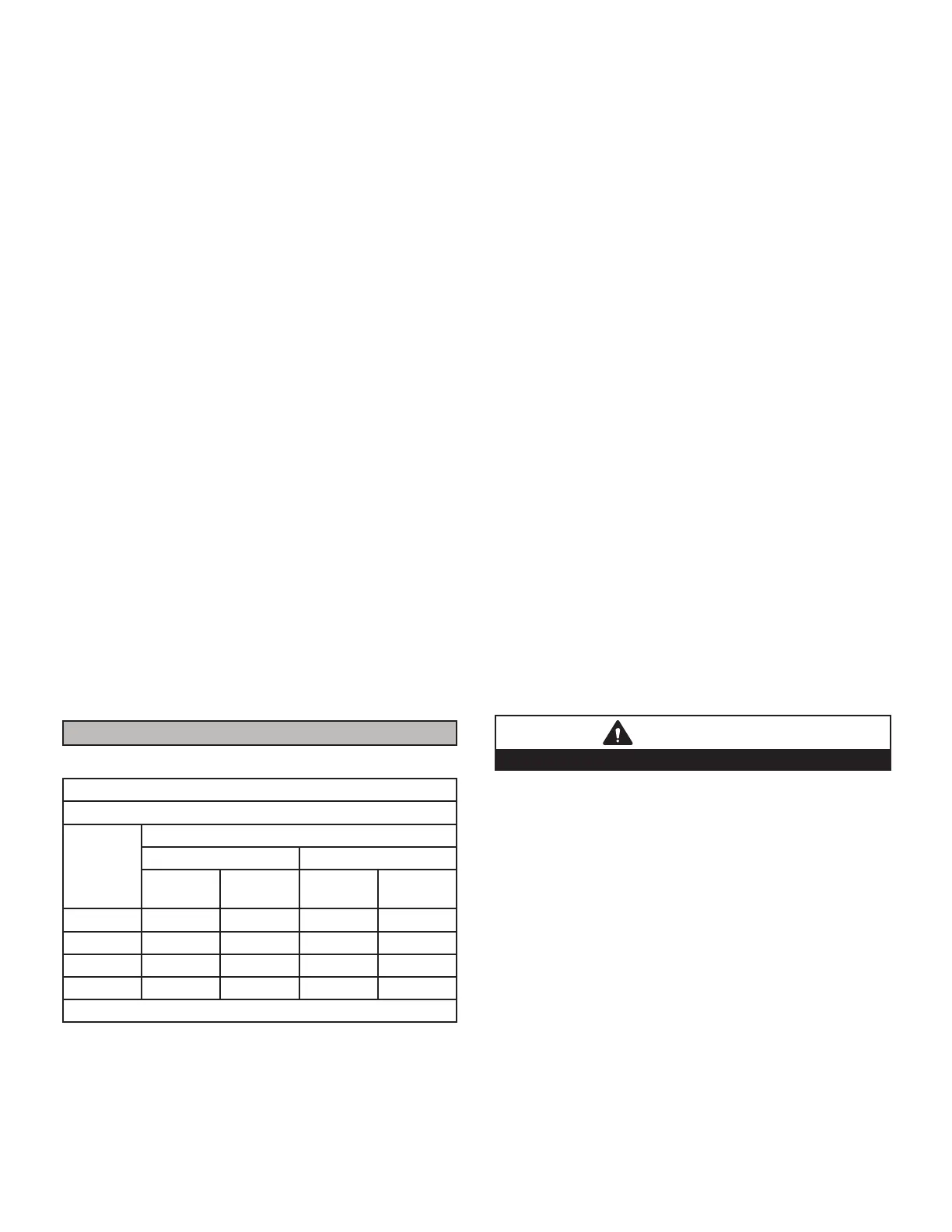
TABLE 28
GAS METER CLOCKING CHART
SLP99
Unit
Seconds for One Revolution
Natural LP
1 cu ft
Dial
2 cu ft
Dial
1 cu ft
Dial
2 cu ft
Dial
-070 55 110 136 272
-090 41 82 102 204
-110 33 66 82 164
-135 27 54 68 136
Natural-1000 btu/cu ft LP-2500 btu/cu ft
Furnace should operate at least 5 minutes before check-
ing gas ow. Determine time in seconds for two revolu-
tions of gas through the meter. (Two revolutions assures
a more accurate time.) Divide by two and compare to time
in TABLE 28. If manifold pressure matches TABLE 29 and
rate is incorrect, check gas orices for proper size and
restriction. Remove temporary gas meter if installed.
NOTE - To obtain accurate reading, shut o all other gas
appliances connected to meter.
Supply Pressure Measurement
A threaded plug on the inlet side of the gas valve provides
access to the supply pressure tap. Remove the thread-
ed plug, install a eld-provided barbed tting and connect
a manometer to measure supply pressure. Replace the
threaded plug after measurements have been taken.
Manifold Pressure Measurement (FIGURE 57)
To correctly measure manifold pressure, the dierential
pressure between the positive gas manifold and the neg-
ative burner box must be considered. Use pressure test
adapter kit (available as Lennox part 10L34) to assist in
measurement.
1 - Remove the threaded plug from the outlet side of
the gas valve and install a eld-provided barbed
tting. Connect measuring device “+” connection to
barbed tting to measure manifold pressure.
2 - Tee into the gas valve regulator vent hose and
connect measuring device “-” connection.
3 - Start unit on low heat (35% rate) and allow 5 minutes
for unit to reach steady state.
4 - While waiting for the unit to stabilize, notice the
ame. Flame should be stable and should not lift
from burner. Natural gas should burn blue.
5 - After allowing unit to stabilize for 5 minutes, record
manifold pressure and compare to value given in
TABLE 29.
6 - Repeat steps 3, 4 and 5 on high heat.
7 - Shut unit o and remove manometer as soon as
an accurate reading has been obtained. Take care
to remove barbed tting and replace threaded plug.
8 - Start unit and perform leak check. Seal leaks if
found.
CAUTION
Do not attempt to make adjustments to the gas valve.
Operating Pressure Signal (Delta P) Measurement
(FIGURE 58)
Operating pressure signal can be taken while the mani-
fold pressure check is taken (using two measuring devic-
es). Or, taken after the manifold pressure measurement is
complete.
1 - Tee into the negative line between the gas valve and
pressure switch and connect to measuring device
negative “-”.
2 - Tee into the positive line between the gas valve and
pressure switch and connect to measuring device
positive “+”.
3 - Start unit on low heat (35% rate) and allow 5 minutes
for unit to reach steady state.
4 - After allowing unit to stabilize for 5 minutes, record
operating pressure signal and compare to value
given in TABLE 29. Repeat steps 3 on 4 high heat.
 Loading...


