Page 54
Pressure Switches (Two)
The pressure switches are located on the cold end header
box. These switches check for proper combustion air in-
ducer operation before allowing ignition trial. The switch-
es are factory-set and require no adjustment. Pressure
switch tubing installation is critical for safe operation. See
FIGURE 59.
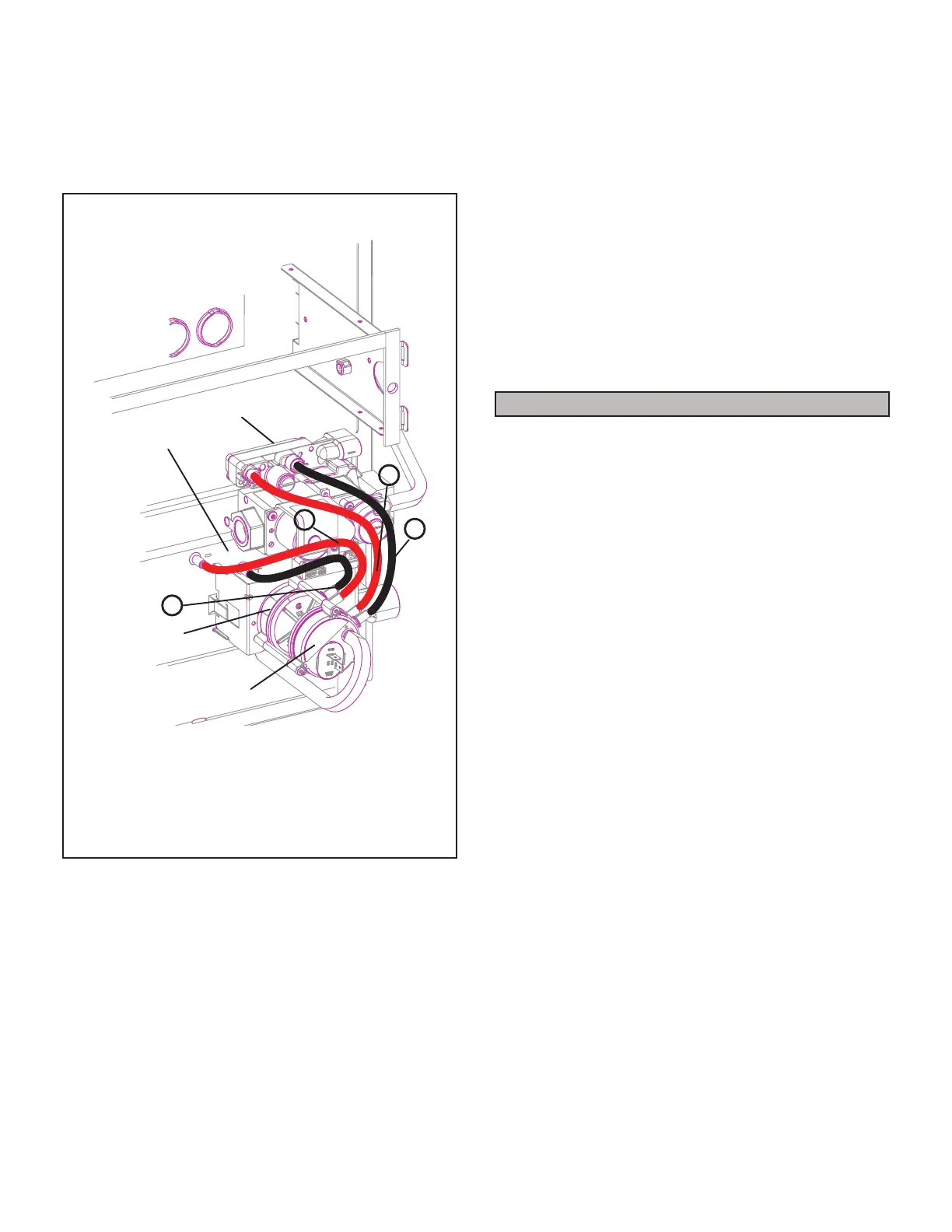
PRESSURE SWITCH TUBING INSTALLATION
(shown in upflow position)
Gas Valve
Cold End Header Box
High-Fire
Pressure Switch
Low-Fire
Pressure Switch
1
2
3
4
1 - Black tubing from front port on low-fire pressure switch to
positive port on the gas valve.
2 - Red and black tubing from rear port on low-fire pressure
switch to the negative port on the gas valve.
3 - Red and black tubing from front port on high-fire pressure
switch to negative port on cold end header box.
4 - Black tubing from rear port on high-fire pressure switch to
positive port on cold end header box.
FIGURE 59
Temperature Rise
After the furnace has been started and supply and return
air temperatures have been allowed to stabilize, check
the temperature rise with the unit operating at 100 per-
cent ring rate. See “Duct System” on page 10 for in-
stalling the optional discharge air sensor (shipped with the
furnace) used to measure temperature rise. If necessary,
adjust the blower speed to maintain the temperature rise
within the range shown on the unit nameplate. See TABLE
24 on page 48 for allowable heating speeds.Increase
the blower speed to decrease the temperature. Decrease
the blower speed to increase the temperature rise. Failure
to adjust the temperature rise may cause erratic limit op-
eration.
Electronic Ignition
The integrated control has an added feature of an inter-
nal Watchguard control. The feature serves as an auto-
matic reset device for ignition control lockout caused by
ignition failure. This type of lockout is usually due to low
gas line pressure. After one hour of continuous thermostat
demand for heat, the Watchguard will break and remake
thermostat demand to the furnace and automatically reset
the control to begin the ignition sequence.
Exhaust and Air Intake Pipe
1 - Check exhaust and air intake connections for
tightness and to make sure there is no blockage.
2 - Are pressure switches closed? Obstructed exhaust
pipe will cause unit to shut o at pressure switches.
Check termination for blockages.
3 - Reset manual ame rollout switches on burner box
cover.
Heating Sequence of Operation
The integrated control initiates a pressure switch calibra-
tion at the initial unit start-up on a call for heat. The ignition
control will also initiate a calibration any time main power
is turned o and back on and a heating demand is pres-
ent . Additional calibrations may be initiated by the ser-
vice technician during eld test sequence. The following
heating sequence of operation assumes completion of a
successful calibration.
NOTE - In communicating applications, the sequence of
operation is the same but all DIP switch settings are ove-
ridden by the thermostat.
NOTE - The thermostat selection DIP switch on the inte-
grated control is factory-set in the “TWO-STAGE” position.
Applications Using a Two-Stage Thermostat
A - Heating Sequence -- Control Thermostat Selection
DIP switch in “Two-Stage” Position (Factory Setting)
1 - On a call for heat, thermostat rst-stage contacts
close sending a signal to the integrated control. The
integrated control runs a self-diagnostic program
and checks high temperature limit switches for
normally closed contacts and pressure switches
for normally open contacts. The combustion air
inducer is energized at ignition speed, which is
approximately the same as the inducer speed at 70
percent ring rate.
2 - Once the control receives a signal that the low-
re pressure switch has closed, the combustion
air inducer begins a 15-second pre-purge in the
ignition speed.
3 - After the pre-purge is complete, a 20-second initial
ignitor warm-up period begins. The combustion air
inducer continues to operate at the ignition speed.
4 - After the 20-second warm-up period has ended,
the gas valve is energized and ignition occurs. At
the same time, the control module sends a signal to
begin an indoor blower 30-second ON-delay. When
the delay ends, the indoor blower motor is energized
at a speed that matches the ring rate. After the
10-second ignition stabilization delay expires, the

 Loading...